
Abstract
Due to energy crises in the future, much effort is being directed towards alternate sources. Solar energy is accepted as a novel substitute for conventional sources of energy. Out of the long list of various types of solar cells available on the market, solid state photoelectrochemical solar cells (SSPECs) and dye sensitized solar cells (DSSCs) are proposed as an alternative to costly crystalline solar cell. This review provides a common platform for SSPECs and DSSCs using polymer electrolyte, particularly on polyethylene oxide (PEO)-based polymer electrolytes. Due to numerous advantageous properties of PEO, it is frequently used as an electrolyte in both SSPECs as well as DSSCs. In DSSCs, so far high efficiency (more than 11%) has been obtained only by using volatile liquid electrolyte, which suffers many disadvantages, such as corrosion, leakage and evaporation. The PEO-based solid polymer proves its importance and could be used to solve the problems stated above. The recent developments in SSPECs and DSSCs using modified PEO electrolytes by adding nano size inorganic fillers, blending with low molecular weight polymers and ionic liquid (IL) are discussed in detail. The role of ionic liquid in modifying the electrical, structural and photoelectrochemical properties of PEO polymer electrolytes is also described.
Export citation and abstract BibTeX RIS

Content from this work may be used under the terms of the Creative Commons Attribution-NonCommercial-ShareAlike 3.0 licence. Any further distribution of this work must maintain attribution to the author(s) and the title of the work, journal citation and DOI.
1. Introduction
One of the prime areas of present worldwide research is related to the future energy crisis. Fossils fuels, supplying ∼80% of all energy consumed worldwide, are facing rapid resource depletion. Because of a growing demand for energy, there is an urgent need for environmentally friendly sustainable energy technologies. Renewable energy, which includes solar energy, is a novel alternative and seems to be a promising candidate to solve this problem. In the photovoltaic industry, today the main barrier is directly related to the high cost of the electricity generated by solid state solar cells (SSSCs) based on crystalline silicon. Crystalline silicon accounted for nearly 74% of solar cell production, but due to high cost, modern research is diverted towards low cost alternatives. A shortage of Si-based raw materials to manufacture solar cells is also just around the corner. Therefore, new types of low cost solar cells are anticipated [1, 2].
As far as electrochemical applications using polymer electrolyte is concerned, polyethylene oxide (PEO) is straightforward due to its conductive properties. Due to other useful properties, like the ease of film formation, excellent complexation with ionic salts, and low glass transition temperature, it is frequently used in lithium batteries, supercapacitors and photoelectrochromic display devices [3–5]. It is well known that polyethers, like PEO, may give conducting solutions when mixed with an alkali metal salt. The solvating capabilities of the PEO-based polymer are due to the unpaired electrons on the ether oxygen atoms, which act as donors for the alkali cations. The higher transference number for the anions observed in these systems, which is not desirable in the applications where the cations are the active species (like in lithium rechargeable batteries), is very attractive in electrochemical photovoltaic cells, where the anions react at the photoelectrode. Hence, several attempts have been made to develop the solar cell using PEO-based solid state electrolytes.
In this review, we focus our attention on solid state photoelectrochemical solar cells (SSPECs) and dye sensitized solar cells (DSSCs) using solid polymer electrolyte based on polyethylene oxide (PEO)-based polymer. The recent advancement and future prospect of SSPECs and DSSCs using PEO-polymer electrolyte are also presented in detail. The applications of modified PEO-polymer electrolytes by adding different additives, like inorganic fillers, plasticizers, ionic liquid, etc in SSPECs and DSSCs are also presented.
The basic difference between SSPECs and DSSCs are shown in figure 1. SSPECs contain a semiconducting substrate onto which a polymer electrolyte containing redox couple is sandwiched (figure 1(a)), while in DSSCs a layer of dye that works as a sensitizer is soaked onto the surface of wide band gap porous semiconducting electrodes (figure 1(b)), and finally polymer electrolyte containing redox couple is sandwiched between a dye sensitized porous semiconducting electrode and a platinized counter electrode. The primary difference is in the light absorbing material and its energetics. However, the role of the polymer electrolyte remains almost the same as a channel for the redox couple. In subsequent paragraphs, we discuss the basic principle of the two and the functioning of the PEO-based polymer electrolytes therein.

Figure 1 Schematic configuration of a solid state photoelectrochemical solar cell (SSPEC, panel (a)) and a dye sensitized solar cell (DSSC, panel (b)) [5].
2. Basic principle of a solid state photoelectrochemical solar cell and a dye sensitized solar cell
2.1. Principle of a solid state photoelectrochemical (SSPEC) solar cell
After the discovery of the photoelectric effect, researchers and engineers have been infatuated with the idea of converting light into electric power or chemical fuels. Their common dream is to capture the energy that is freely available from sunlight and turn it into the valuable and strategically important asset that is electric power. Photovoltaic devices are based on the concept of charge separation at a single junction, a hetero-junction between two different type (n- and p-type) semiconductor or semiconductor-metal (Schottky) junctions.
The foundation of modern photo-electrochemistry, marking its change from a mere support of photography to a thriving research direction on its own, was laid down by the work of many famous groups [6–10], which present the detailed electrochemical and photo-electrochemical studies of the semiconductor–electrolyte interface. Research on photo-electrochemical cells went through a frantic period after the oil crisis in 1973, which stimulated a worldwide quest for alternative energy sources.
In photo-electrochemical cells, the junctions are semiconductor–electrolyte interfaces. The simplest device consists of a semiconducting electrode, a metallic electrode and an electrolyte, as shown in figure 1(a). The operation of a photo-electrochemical cell can be explained on the basis of the energy level diagram shown in figure 2.

Figure 2 Energy level diagram showing the conduction mechanism in a SSPEC.
In the electrolyte, the energy at which electrons must be provided to drive the electrochemical reaction is known as the redox potential and is usually referenced to the normal hydrogen electrode (NHE) or saturated calomel electrode (SCE). The energy position at which the conduction and valence bands for n- and p-type semiconductors, respectively, intercept the solid electrolyte interface is known as the flat band potential V fb . The flat band potential is a very useful quantity in photo-electrochemistry as it facilitates the location of the energetic position of the valence and conduction band edge of a given semiconductor material. It is obtained by measuring the capacity of the semiconductor–electrolyte junction. The semiconductor can be used as a light sensitive anode or cathode depending on whether it is n- or p-type, respectively.
The operational principle of the SSPEC is shown in figure 2. Photons of energy exceeding that of the band gap generate electron–hole pairs are separated by the electric field present in the space-charge layer. The negative charge carriers move through the bulk of the semiconductor to the current collector and the external circuit. The positive holes are driven to the surface where they are scavenged by the reduced form of the redox relay molecule and oxidize it. The oxidized form is reduced back to redox relay molecules by the electrons that re-enter the cell from the external circuit. Much of the work on regenerative cells has focused on electron-doped (n-type) II/VI or III/V semiconductors using electrolytes based on sulfide/polysulfide, vanadium(II)/vanadium(III) or I 2/I – redox couples. Conversion efficiencies of up to 19.6% have been reported for multi-junction regenerative cells [6].
2.2. Principle of dye sensitized solar cells (DSSCs)
Grätzel introduced a new type of solar cell in 1991, which consists of nanoporous wideband semiconductors films immersed in dye solution, and these made a breakthrough in the photovoltaic area. This solar cell is termed a Grätzel cell or dye sensitized solar cell (DSSC). Academic and commercial interest has been attracted to DSSCs because of their high efficiency, potential low-cost and simple assembly.
A DSSC is composed of a nano-crystalline semiconductor oxide film electrode, dye sensitizers, electrolytes, a counter electrode and a transparent conducting substrate. Typically, dye-derived nano-crystalline semiconductor films were used as a photo-anode, platinized counter electrode, filled with electrolyte solution containing I 3 −/I − redox couple in organic solvent. The operating mechanism of the solar cells is shown in figure 3. Under the irradiation of sunlight, the dye molecules become photo-excited and ultraquickly inject an electron into the conduction band of the semiconductor electrode, then the original state of the dye is restored by electron donation from the electrolyte, usually the solution of an organic solvent or ionic liquid solvent containing the I 3 −/I − redox system.

Figure 3 Structure and operating principle of a DSSC.
The regeneration of the sensitizer by iodide intercepts the recapture of the conduction band electron by the oxidized dye. The iodide is regenerated, in turn, by the reduction of triiodide at the counter electrode, the circuit being completed through the external load. The voltage generated under illumination corresponds to the difference between the Fermi level of the electron in the semiconductor electrode and the redox potential of the electrolyte. Overall, electric power is generated without permanent chemical transformation.
2.3. Fabrication of the DSSC
In our laboratory, we have successfully developed DSSC assembly using fluorine-doped SnO 2 conducting glass as the substrate. TiO 2 colloidal paste to develop porous TiO 2 film was obtained from Ti-nanoxide-D, Solaronix, Switzerland, while iodide sources, iodine (I 2) and H 2 PtCl 6 solution were supplied by Sigma-Aldrich company. Low viscosity ionic liquids (ILs) were obtained from C-TRI company, Korea, while dye (535-bisTBA) was obtained from the Solaronix, Switzerland.
First, a blocking layer of Ti(IV) bis(ethyl acetoacetato)-diisopropoxide solution (2 wt%, in 1-butanol) was spread uniformly on the surface of the conducting glass by spin coating, and annealed at 300 °C for 30 min. A layer of Ti-nanoxide-D was then spread on this FTO substrate using the doctor blade method. The thickness of the nanoporous TiO 2 film was controlled by sticking on two Scotch adhesive tapes, each having a thickness ∼50 μm. After removing the adhesive tape, the TiO 2 coated glass plate was calcinated in air for 30 min at 500 °C and then allowed to cool, which gave excellent porous film with good thickness (∼10 μm).
The DSSC of active area ∼0.25 cm 2 was prepared using a dye solution (dissolving 13 mM 535-bisTBA) in distilled ethanol. The TiO 2 electrode was coated with this dye solution by soaking it overnight, washing it in acetone and drying it in N 2 stream. The Pt-counter electrode (CE) was prepared by spin-coating with H 2 PtCl 6 solution (0.05 mol dm −3 in isopropyl alcohol) onto the conductive glass and then sintering at 400 °C for 30 min. Ionic liquid doped polymer electrolyte solution (∼400 μl) was then cast on the TiO 2 electrode using a two-step casting method. The Pt electrode and the dye coated TiO 2 electrodes containing polymer electrolyte/ionic liquid were clamped firmly together and the whole DSSC assembly was dried under vacuum to remove the solvent.
3. Status of solid state photoelectrochemical cells (SSPECs) using a PEO polymer electrolyte
The direct conversion of solar energy to electricity by using a semiconductor/electrolyte interface has been demonstrated by Gerischer and Goberecht [6] and by Ellis et al [7]. The Gerischer cell consist of n-CdSe single crystal photoanode and a doped SnO 2 cathode dipped in an aqueous alkaline electrolyte containing the Fe(CN)6 4−/Fe(CN)6 3− redox couple. The energy conversion efficiency was 5% but the cell performance decreased rapidly due to decomposition of the illuminated semiconductor electrode and evaporation of solvent. Since then, various modifications have been tried on each component of PEC and there are many good reviews. These problems are partly solved by replacing this electrolyte by solid polymer electrolytes.
Initial application of polymer in a photoelectrochemical solar cell (PEC) based on polyethylene oxide (PEO) was performed by Skotheim [8] in 1981 using a PEO:KI:I 2 polymer electrolyte system with n-Si and indium tin oxide (ITO) electrodes. Although this cell could solve the volatility and corrosion problems, their photocurrent (J sc ) and fill factor (FF) remained very poor, i.e. 20 μA cm −2 and 0.25, respectively. This is due to a high recombination rate at the semiconductor interface or low ion mobilities [9]. Skotheim and Inganas [10] later showed that the energy barrier to hole transfer problem could be overcome by using a special coating of Pt on the silicon surface, and using this method they obtained J sc up to 10 mA cm −2 at 1 sun irradiation intensity. Rao et al [11], and Narsaiah et al [12] studied the charge–discharge behaviour of a cell with configuration Na/PEO:salt:I 2/Carbon+electrolyte. Mohamed et al [13] reported a solid state photoelectrochemical cell using PEO:NaI with different salts. Yohannes and Iganas [14] fabricated an SSPEC using PEO complexed with an I −/I 3 − redox couple, while Bhattacharya et al [15] reported an SSPEC using PEO:NH 4 I/I 2 solid polymer electrolyte. Following the same strategy recently, Arof et al [5, 16] constructed cells with configuration ZnSe/PEO-Chitosan:NH 4 I/I 2, ZnTe/PEO-Chitosan:NH 4 I/I 2 blend electrolytes. However, the performance of the SSPECs reported above is still low (<1%) in comparison with the same cells using liquid electrolyte. The possible reasons are
- low ionic conductivity (σ) in comparison to liquid electrolyte;
- rubbery type morphological structure of these polymer electrolytes, which reduces the contact area between the electrode and electrolyte, i.e. the active interface, and
- high charge recombination rate at the semiconductor interface.
4. Status of dye sensitized solar cells (DSSCs) using a solid PEO-based polymer electrolyte
The future of photovoltaics is believed to be the dye-sensitized solar cell (DSSC), which is relatively new, with a completely different approach. In the DSSC (figure 1(b)), visible light energy could be converted into electrical energy through charge separation in sensitizer dyes adsorbed on a wide band gap semiconductor. It comprises a transparent conducting oxide (TCO) electrode, a platinum-coated counter electrode and an electrolyte containing redox couple sandwiched between these electrodes [17]. One unique characteristic of this solar cell is the ease with which it is produced and its relatively good efficiency using low cost materials [18, 19]. Additionally, it shows 10–20% more electricity than a conventional crystalline Si-solar cell module in large-scale outdoor performance [20].
In DSSCs, the popular alternatives that are commonly being tested to replace the liquid electrolytes are
- hole conducting solid electrolytes;
- gel/quasi solid state electrolytes;
- polymeric solid state electrolytes.
The solid electrolytes (i) and (ii) stated above are not being discussed here as each of these has its own broad area, which is not in the scope of our discussion. The polymeric solid electrolytes (iii) are of special interest because of their many advantageous properties, like low cost, easy thin film formation and overall good device performance. The highest reported efficient DSSC contains volatile organic solvent, which still has a drawback for long-term practical operation [17–19]. Moreover, the corrosion of iodine on Pt electrolyte, leakage and evaporation of solvent are also additional barriers. Using solid polymer electrolyte, one can overcome these problems. Among all polymer electrolytes, PEO-based polymer electrolyte has already shown excellent performance in different electrochemical application areas [2, 3]. The use of PEO-based electrolyte in PEC also indicated its possibilities in photovoltaic applications. In DSSCs, it is also considered to be a novel candidate due to better stability and performance, and hence a large number of review articles are already available [1, 21, 22]. Passing through the literature, it is quite difficult to distinguish between DSSCs based on low molecular weight PEO (also known as oligomer electrolytes) and high molecular weight PEO. Here, we offer a schematic representation of a DSSC developed to date using PEO-based polymer electrolytes. To avoid confusion, here we divide PEO-based DSSCs into the following two categories:
- DSSCs containing PEO with low molecular weight (molecular weight less than 50 000 g mol −1, oligomers, liquid in nature at RT).
- DSSCs using high molecular weight PEO (molecular weight more than 1000 000 g mol −1, solid powder at RT).
4.1. DSSCs using low molecular weight PEO (oligomers) as electrolyte
After the successful demonstration of a DSSC by the Grätzel group in 1991, many extensive investigations have been carried out in all aspects of DSSCs. As far as solid PEO polymer electrolyte is concerned, it is well known that due to the high crystallinity of PEO, it is not easy to get perfect soaking of this electrolyte at the electrode. This results in poor electrode–electrolyte contact and hence the overall DSSC performance is reduced [21, 22]. To resolve this problem, Kang et al have proposed an oligomer-based approach (low molecular weight PEO) [23–28]. They used a series of low molecular weight PEO-based oligomers with various iodide sources, such as ionic liquid (IL), potassium iodide (KI), sodium iodide (NaI) and lithium iodide (LiI), and they obtained a high efficiency DSSC. To obtain high ionic conductive polymer electrolyte, this group added a variety of additives, such as fumed silica, silica nanoparticles, glutaraldehyde (GA), propylene carbonate (PC) and ethylene carbonate (EC) in low molecular weight PEO to enhance J sc and overall efficiency. They also demonstrated that for better interfacial contact, it is necessary that the coil size of the PEO should be less than the pore size of the nanoporous TiO2 electrode (∼16 nm). The coil size, as estimated by the radius of gyration of the polymer, varies with its molecular weight/chain length. The coil size of the PEO oligomer with a molecular weight (Mw) of 1000 g mol −1 (PEG 1000) in solution is less than 3 nm and hence can easily penetrate the pores of the mesoporous titania electrode. As a result, good interfacial contact with deep penetration could be obtained, which resulted in a highly efficient DSSC (3–6% at 100 mW cm −2). Following this strategy, Ren et al [29] developed PEO-based oligomer electrolytes having Mw 2000 and 1500 g mol −1 (PEO 2000, PEO 1500) containing plasticizers (PC, EC) as additives. Based on this electrolyte, a DSSC with 3.6% efficiency at 27 mW cm −2 has been reported. Recently, Akhtar et al [30,31] used PEG-based oligomers having Mw ∼100 000, 20 000 g mol −1 (PEG10 000, PEG20 000) and TiO 2 nanotube (TNT), heteropolyacid (HPA) as additives to develop an efficient DSSC having 4.43% and 3.1% efficiency at 100 mW cm −2, respectively. The overall data using the oligomer approach electrolyte are listed in table 1.
Table 1. The collective data of DSSCs using low molecular weight PEO (oligomer)-based polymer electrolytes.
| PEG 1000:IL:I 2 | – | ∼10−3 | 9.53 | 0.57 | 62 | 3.34 | 100 | [23] |
| PEO+PPG:KI:I 2 | – | ∼10−5 | 11.2 | 0.72 | 48 | 3.84 | 100 | [25] |
| PEGDME:IL/KI:I 2 | silica | ∼10−3 | 9.58 | 0.67 | 70 | 4.50 | 100 | [26] |
| PEG 1000:KI:I 2 | GA | ∼10−3 | 9.48 | 0.64 | 60 | 3.64 | 100 | [27] |
| PEGDME:IL/KI:I 2 | – | ∼10−3 | 15.24 | 0.62 | 66 | 5.88 | 100 | [28] |
| PEO 2000: LiI:I 2 | PC, EC | ∼10−3 | 2.8 | 0.58 | 60 | 3.60 | 27 | [29] |
| PEG 100000 :LiI:I 2 | TNT, TBP | ∼10−3 | 9.3 | 0.72 | 65 | 4.43 | 100 | [30] |
| PEO 20000 :LiI:I 2 | HPA, TBP | ∼10−3 | 9.7 | 0.52 | 65 | 3.10 | 100 | [31] |
4.2. DSSCs using high molecular weight PEO as the electrolyte (without any additives)
The first DSSC based on high molecular weight (Mw=1.3×10⁶ g mol −1) PEO-based solid electrolyte without any dopants was reported in 1999 by Nogueira et al [32], when they used a modified polymer PEO-epychlomer (referred as PEC hereafter) with sodium iodide (NaI) and iodine (I 2) as the redox couple and conducting poly(o-methoxy aniline) as the sensitizer. The reported efficiency of their cell was 1.6×10⁻⁴% at 120 mW cm −2. Such a low efficiency can be attributed to the
- highly crystalline matrix of the polymer;
- low ionic conductivity (σ) of the polymer electrolyte (∼10−5 S cm −1) in comparison with the liquid electrolyte, where the σ value lies between 10−1 and 10−2, and
- incomplete wetting of the semiconductor nanoparticles at the anode by the polymer electrolyte.
Later, this group used the same polymer electrolyte, i.e. PEO-epychlomer (PEC), and ruthenium-based dyes. The best DSSC efficiencies they reported were 1.6 and 2.6% at 100 and 10 mW cm −2 light intensity, respectively [33–35]. In 2005, Kim et al [36] reported a DSSC consisting of PEO/NaI:I 2 polymer electrolyte and ruthenium-based dye, which shows efficiency of 0.07% at 10 mW cm −2 light intensity. As discussed above, according to the model proposed by Kang et al [23–28] in high molecular weight PEO (Mw ∼1000 000 g mol −1), the approximate coil size is ∼63 nm, but it is ∼19 nm for a molecular weight of 100 000 g mol −1 while the estimated TiO 2 pore size is 10–15 nm. For this reason, for high molecular weight PEO, it is not easy to penetrate the TiO 2 pore, which resulted in low efficiency. However, the same group reported [37] an efficient DSSC (2.04% at 100 mW cm −2 light intensity) containing a high molecular weight PEO:KI/I 2 system (Mw=1000 000 g mol −1). The collective data of DSSCs using the aforementioned polymer electrolyte systems are shown in table 2.
Table 2. The collective data of DSSCs using high molecular weight PEO-based polymer electrolytes without adding any additives.
| PEO-pychlomer:NaI:I 2 (PEC) | NaI | 1.0 | 0.012 | 0.048 | 32 | 1.6×10⁻⁴ | 120 | [32] |
| PEO-pychlomer:NaI:I 2 | NaI | 1.5 | 0.5–4.2 | 0.74–0.82 | 73–47 | 2.6–1.6 | 10,100 | [33, 34] |
| PEO:NaI:I 2 | NaI | 0.16 | 0.5 | 0.54 | 26 | 0.07 | 10 | [36] |
| PEO:KI:I 2 | KI | 8.3 | 6.12 | 0.59 | 56 | 2.04 | 100 | [37] |
4.3. A DSSC using high molecular weight PEO as electrolyte (with additives)
The DSSC proposed by Nogueira et al [33] clearly shows that the overall efficiency has already reached the limit for the system based on a polymer-iodide salt/iodine complex. The use of only high molecular weight PEO as the electrolyte cannot result in higher values than this. For further improvement in the efficiency of the DSSC, it is necessary to modify the electrolytes by adding popular additives. In this connection, many additives, such as inorganic nanoparticles, plasticizers, copolymers and ionic liquids, have been tried, which shows that further improvement of DSSC efficiency could be possible.
4.3.1. Adding nanosize inorganic fillers as additives in polymer electrolytes
The high crystallinity and too low ambient conductivity of a PEO-based electrolyte acts as a barrier to using it in DSSCs as the electrolyte. The addition of nano-inorganic fillers are well-known successful approaches to enhance the conductivity and mechanical properties of polymer electrolyte film, which is necessary for device application [38–40]. It is generally recognized that the improvement in ionic conductivity (σ) in PEO-polymer electrolytes comes from the suppression of crystallinity and the promotion of an amorphous region. In this direction, Falaras et al [41–44] have already proposed highly efficient DSSCs based on nanocrystalline porous TiO 2 film, ruthenium complex based different dyes, a Pt counter electrode and solid polymer electrolytes PEO-LiI:I 2/titania. They could successfully reduce the crystallinity of the PEO polymer electrolyte and reported that introduction of titania nanoparticles reduces the crystallinity, which in turn enhances the ionic conductivity (σ) as well as providing a three-dimensional path (figure 4) for easy movement of the redox couple (I −/I 3 −) into the polymer matrix, and hence they achieved efficiency as high as 4.2% at 65.6 mW cm −2 [43].

Figure 4 Two-dimensional AFM topographic images of a PEO:LiI/I 2+titania composite polymer electrolyte system. The arrow indicates the distribution of titania particles [43].
Following this approach, recently Chen et al [45] reported an efficient DSSC (4.06% at 75 mW cm −2) using nanoparticles of TiO 2 as the filler in a blend-modified PEO–VDF polymer electrolyte matrix.
4.3.2. Adding plasticizers as additives
As discussed earlier, one of the main approaches was directed towards the reduction of the crystallinity of PEO or lowering its glass transition [46, 47]. The plasticizer, usually a low molecular weight polyether or carbonate, is incorporated in small amounts into the polymeric matrix to increase its segmental motion, which is closely associated with the glass transition temperature. The plasticizers introduce a degree of disorder in the polymer matrix, which is necessary for further improvement of electrical conductivity (σ) and its device application. In DSSCs using PEO polymer electrolyte, many popular plasticizers, like polyethylene glycol (PEG), polypropylene glycol (PPG), ethylene carbonate (EC), 1, 2-dimethoxyethane (DME), γ-butyrolactone (BL) and propylene carbonate (PC), have already shown their importance in enhancing ionic conductivity by reducing the crystallinity [46–52].
4.3.2.1. Plasticizers in the polymer electrolyte matrix
It is known from the literature that blending two semicrystalline polymers like PEO with PVDF (polyvinylidene fluoride) or polysiloxane (PS) with PPG (polypropylene glycol) improves the ionic conductivity (σ) and electrode/electrolyte interface properties due to changes in the polymer chains and crystalline phase.
To introduce more amorphous reason into the PEO matrix, it is necessary to introduce a certain degree of disorder in the structure. Adding plasticizers is a novel approach that fulfils the requirement needed for an efficient DSSC using apolymer electrolyte [46]. Haque et al [47] reported an efficient DSSC that shows high efficiency of 5.3% at 10 mW cm −2 using plasticizers EC&PC in a 1:1 ratio in a PEC:NaI:I 2 system. Later, Ileperuma et al [48] used PC, EC plasticizers doped PEO:KI:I 2 polymer electrolyte system that shows high conductivity (2.2×10⁻³ S cm −1) and DSSC efficiency of 0.6% at 100 mW cm −2. Anandan et al [49, 50] doped known plasticizers like heteropolyacid (HPA), benzidine (Bz) in PVDF:KI:I 2 and PEC:KI:I 2+NPT polymer electrolyte matrix and achieved efficiencies of 2.77 and 3.43%, respectively, at 15 mW cm −2. Using the same strategy, Ganesan et al [51, 52] used diphenyl amine (DPA), 2,6-bis(N-pyrazolyl) pyridine (BNPP) into PEO:KI:I 2 polymer electrolyte matrix and the reported efficiencies were 6.5 and 8.8% at 60 and 80 mW cm −2 light intensity, respectively. Freitas et al [53, 54] reported an efficient (efficiency 3% at 100 mW cm −2) stable (upto 30 days) DSSC using plasticizers γ-butyrolactone (BL) in PEC containing NaI or LiI and I 2 system. Recently, an efficient DSSC (4.03% at 100 mW cm −2) was claimed by Flores et al [55] applying plasticizer poly(ethyleneglycol)dibenzoate (PEG-diB) in PEO-epychlomer (PEC):NaI:I 2 matrix. Additionally, this group successfully demonstrated a large area (4.5 cm 2) DSSC module in which they connected 13 cells in series (figure 5). They obtained an average efficiency of 0.9% per cell operated in outdoor conditions [56]. Benedetti et al demonstrated an efficient DSSC (efficiency 3.7% at 100 mW cm −2) employing a PEO copolymer:LiI:I 2 electrolyte containing plasticizers γ-BL and 12-crown-4 ether as additives [57]. The overall increase in efficiency of the polymer electrolyte systems stated above are based on the reduction in crystallinity of the PEO polymer matrix by adding known plasticizer, as stated above, and good ionic conductivity (σ) (10−5 to 10−3 S cm −1).

Figure 5 DSSC module where 16 solar cells are connected in series under irradiation of a 50 W fluorescent lamp [56].
4.3.2.2. Plasticizers in polymer blend electrolyte
Blending of polymer in a PEO matrix is also a well-known method to further lower the T g value of the PEO, which is a known barrier for conductivity enhancement [44–46]. Kang et al [58] reported a DSSC (1.39% at 60 mW cm −2) consisting of PEO blend polysiloxane (PS) polymer electrolyte plasticized with PC, EC, γ-BL and PEG. Recently, Lee et al [58] achieved high conductivity in a PEO-PDMS blend system with LiI salt and they obtained efficiencies of 0.63% at 100 mW cm −2 and 1.02% at 10 mW cm −2. The enhancement of conductivity has been attributed to the decrease in crystallinity and increase in the number of charge carriers provided by the plasticizers.
4.3.2.3. Plasticizer with nanofiller in polymer blend electrolyte
Adding different nanofillers (nano size particles of inorganic materials) into blend plasticized PEO polymer electrolyte matrix is also a popular approach to achieve high efficiency DSSC. In this continuation, Zhao and co-workers [59–62] reported results of the study oD nanoparticles of SiO 2 and carbon as additive in PEO–PVDF and PVDF–HFP polymer electrolytes plasticized with PC and DME. Later they showed that ultrasonic treatment and adding some other additives, like water and ethanol, to this polymer electrolyte could also be a novel approach to enhance DSSC efficiency. The collective data of DSSCS that fall within this category are shown in table 3.
Table 3. The collective data of DSSCS using high molecular weight PEO and PEO-blend polymer electrolytes with plasticizers as additives.
| PEC:NaI:I 2 | PC, EC | ∼10−5 | 6.10 | 0.80 | 53 | 2.5 | 100 | [46] |
| PVDF:KI:I 2 | HPA | ∼10−5 | 3.90 | 0.42 | 25 | 2.7 | 15 | [49] |
| PEC:KI:I 2 | Bz | ∼10−4 | 5.53 | 0.37 | 25 | 3.4 | 15 | [50] |
| PEO: KI:I 2 | DPA | ∼10−5 | 10.2 | 0.81 | 47 | 6.5 | 60 | [51] |
| PEO:KI:I 2 | BNPP | ∼10−5 | 21.3 | 0.70 | 47 | 8.8 | 80 | [52] |
| PEO:KI:I 2 | PC, EC | ∼10−3 | 0.67 | 0.67 | – | 0.6 | 60 | [53] |
| PEC:NaI:I 2 | γ-BL | ∼10−4 | 9.0 | 0.76 | 47 | 3.0 | 100 | [54] |
| PEC:NaI:I 2 | γ-PEG-diB | ∼10−4 | 9.6 | 0.84 | 49 | 4.0 | 100 | [55] |
| PEC:LiI:I 2 | crown ether, γ-BL | ∼10−3 | 11.4 | 0.78 | 42 | 3.7 | 100 | [57] |
| PEO : PS | PC, EC, γ-BL, PEG | ∼10−3 | 2.0 | 0.60 | 68 | 1.3 | 60 | [58] |
| PEO:PVDF:LiI:I 2+ * NPC | PC, DME | ∼10−4 | 7.90 | 0.67 | 58 | 4.8 | 65.2 | [59] |
| PEO : PVDF-HFP:LiI:I 2+ * NPS | PC, DME | ∼10−3 | 6.39 | 0.54 | 65 | 3.6 | 62.5 | [60] |
| PEO : PVDF-HFP:LiI:I 2+ * NPT | PC, DME | ∼10−4 | 7.34 | 0.53 | 67 | 4.2 | 65.2 | [61] |
| PEO:PVDF:LiI:I 2+ * NPT | PC, DME | ∼10−3 | 12.3 | 0.56 | 51 | 3.9 | 93.2 | [62] |
4.3.3. Adding ionic liquid as additive
Ionic liquids (ILs) are a kind of new material that prove their importance in different areas of materials science. Recently, there has been increased interest in research towards using ILs in various electrochemical applications [63–65]. Due to the variety of useful properties, researchers frequently use them in different areas and hence it is not possible to cover the applications of these ILs in a single topic. Here, we focus on their use in the modification of PEO polymer electrolyte and their possible application in dye sensitized solar cells (DSSCs).
In DSSCs, ILs are mostly used as a replacement for volatile organic solvents. In DSSCs using PEO polymer electrolyte, ILs are considered as a novel candidate because they have ionic conduction properties (composed of ions) as well as other useful features, like low vapour pressure and non flammability [66–70]. Apart from these advantages, the liquid nature at room temperature of most of these ILs is the biggest disadvantage. Therefore, in order to develop a solid electrolyte, one of the novel methods is to dope these ILs in a polymer electrolyte matrix [64, 65].
To develop efficient DSSCs, our group has already created a series of novel polymer electrolytes based on a 'low viscosity IL-doped high molecular weight PEO polymer electrolyte' [71–82].
It is known that the ionic conductivity (σ) of polymer electrolyte is closely related to viscosity (η) by the following equations:

and

where n, q and μ are defined as the number of ionic charge carriers, columbic charge and mobility of the species, respectively. Following these equations, it is clear that the mobility (μ) or ionic conductivity (σ) are inversely proportional to the viscosity (η), and hence low viscosity IL is a preferable condition for high ionic conductivity (σ). In the market, a variety of ILs are available according to their various properties. We have tested a series of low viscosity ILs doped into a high molecular weight PEO polymer electrolyte system containing different iodide salts for DSSC applications. The low viscosity ILs used by our group are 1-ethyl 3-methylimidazolium thiocyante (EMImSCN), 1-ethyl 3-methylimidazolium dycynamide (EMImDCN), (1-ethyl 3-methylimidazolium bis(trifluoromethylsulfonyl)imide) (EMImTFSI) and 1-ethyl 3-methylimidazolium trifluoromethanesulfonate (EMImTFO).
It is well known that ILs are composed of ions, i.e. cations as well as anions, that can be dissociated easily. Hence, dispersal of these low viscosity ILs modified the electrical properties of PEO polymer electrolyte by providing additional charge carriers contributing to the conductivity. Figure 6 shows the variation of ionic conductivity with the values of IL concentration in PEO. It is shown that adding ILs into a polymer electrolyte matrix (PEO:KI:I
2 in the present case), the ionic conductivity increases manyfold. The enhancement in ionic conductivity by doping IL could be explained by knowing that the ionic conductivity is governed by equation (
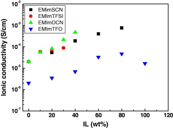
Figure 6 Variation in ionic conductivity (σ) with amount of ionic liquid (IL) added in IL doped solid polymer electrolyte films.
To further affirm the role of low viscosity IL doping into a PEO polymer electrolyte matrix, we have carried out a differential scanning calorimetry (DSC) experiment. Figure 7 shows a typical example of a DSC curve of a PEO:KI:I 2 system doped with low viscosity IL, 1-ethyl 3-methylimidazolium thiocyanate (EMImSCN). The relative percentage crystallinity (χ%) has been calculated by assuming the equation

where ΔH f and ΔH fo are defined as the heat of fusion of the doped complex and a pristine sample, respectively. The calculated parameters using DSC curves are listed in table 4. From this figure and table, it is clear that by adding low viscosity IL both the heat of fusion (ΔH f ) and the melting temperature (T m ) decreases (figure 7(b)). It is also noted that with higher IL content, the values of ΔH f and T m decrease further. In addition, the melting endotherm broadening is observed at higher IL concentration (figure 7(c)). Both the reduced melting temperature and the broadening of the melting endotherm affirmed that adding low viscosity ILs could suppress the crystallinity of the PEO polymer electrolyte. The regular arrangement of the PEO chain partially opens up in the presence of ILs. The greater the IL concentration, the greater the disorder/ amorphicity. Similar observations have been noted in other low viscosity IL–PEO polymer electrolyte systems.

Figure 7 DSC thermograms of (a) PEO:KI:I 2, (b) PEO:KI:I 2+40 wt% EMImSCN ionic liquid and (c) PEO:KI:I 2+80 wt% EMImSCN polymer electrolyte systems with a heating rate of 5 °C min −1 [71].
Table 4. The calculated values of percentage crystallinity (χ%) along with the melting temperature (T m ) and corresponding heat of fusion (ΔH f ) in a PEO:KI:I 2 polymer electrolyte system doped with low viscosity IL (EMImSCN).
| PEO:KI: I 2 (80:20:2.0) | 60.3 | 86.3 | 45.9 | 8.80×10⁻⁶ |
| PEO:KI:I 2+40% IL | 51.7 | 29.0 | 15.4 | 1.90×10⁻⁵ |
| PEO:KI:I 2+80% IL | 45.0 | 16.1 | 8.60 | 7.62×10⁻⁴ |
In general, it is believed that the ionic conductivity (σ) increases as the degree of crystallinity decreases. This phenomenon can be understood as schematically shown in figure 8. In figure 8(a), when PEO is complexed with KI, it shows a partially crystalline nature. The ordering of the polymer chains in localized regions results in the crystallinity of the films. When the IL is added to this system (figure 8(b)), it further modifies the crystallinity. The formerly ordered coils (crystalline region) are expected to become partially disordered, in other words, to adopt a less regular arrangement. Hence, the overall crystallinity of the films is reduced (as evidence by DSC). It is reported that for conduction, ions always prefer amorphous regions and thus the ionic conductivity is enhanced. This decrease in crystallinity (increase in amorphicity) improves the charge transfer mechanism in the device and hence the cell performance is improved.

Figure 8 Schematic diagram showing the effect of doping low viscosity IL into the polymer electrolyte matrix [74].
Doping low viscosity IL also affected the surface property of the polymer electrolyte matrix. Figure 9 shows the tapping mode atomic force microscopy (AFM) images of pure polymer electrolyte (PEO:KI:I 2) and IL (EMImDCN) doped polymer electrolyte film. In the absence of IL, the polymer electrolyte film (PEO:KI:I 2) shows a crater-valley type rough surface (figure 9(a)) with surface roughness RMS=14.45 nm. Incorporation of IL into the PEO:KI:I 2 matrix modifies its structure (figure 9(b)) in such a way that the intensity of the crater-valleys decreases and the surface seems almost smooth with reduced surface roughness of 7.22 nm. Such a decrease in roughness by adding IL clearly indicates that ionic liquid (IL) is incorporated well into the polymer electrolyte matrix and provides a relatively smooth surface matrix. This smooth surface could help in making a good contact at the electrolyte–electrode interface, which further improves the solar cell efficiency. In the case of the other ILs studied by us, similar surface modifications were observed and could be directly correlated to the plasticizing effect of the low viscosity ILs.

Figure 9 Three-dimensional AFM images of (a) PEO:KI:I 2 and (b) PEO:KI:I 2+40 wt% EMImDCN free standing IL-polymer electrolyte films in tapping mode [75].
Further confirmation of surface modifications and crystallinity changes due to the incorporation of ILs in PEO were done with a polarized optical microscope (POM). The PO micrographs are shown in figure 10. Note that pure PEO film (figure 10(a)) clearly shows a semicrystalline nature in which large spherulites are tightly interconnected with each other. Adding NaI and I 2 into the PEO matrix (figure 10(b)), the spherulite size becomes small while the amorphous region (black portion) increases. It was also noticed that doping of low viscosity IL into a polymer electrolyte matrix (PEO:NaI:I 2+IL) shows further improvement in amorphicity where the black portion increases drastically (figure 10(c)). This shows good agreement with our DSC and ionic conductivity measurements. It is also observed that the size and distribution of the spherulites are random and have wide variation. This is the reason for the widening and shifting of the melting peaks, which we could notice under DSC.

Figure 10 Polarized optical microscopy (POM) of (a) pure PEO (b) PEO:NaI:I 2 and (c) PEO:NaI:I 2+IL polymer electrolyte matrix.
The role of ILs in the modification of the electrochemical properties of the PEO has been explored by cyclic voltammetry in an argon (Ar) atmosphere. The electrochemical reaction of low viscosity ionic liquid and polymer electrolyte containing iodide/iodine was carried out. Figure 11 shows typical cyclic voltammograms of the KI:I 2 :IL and PEO:KI:I 2+IL polymer electrolyte membrane. IL (EMImTFSI) doped polymer electrolyte membrane shows (solid line) two well-defined redox peaks. The first peak is assigned to the oxidation of iodide to triiodide, 3I −−2e→I 3 −. At higher potential, the electro-generated triiodide oxidizes to iodine, I 3 −−e −→3/2I 2, and shows a second peak. The IL (EMImTFSI) and PEO are electrochemically inactive in the scanned electrochemical window. In the absence of polymer, KI:I2:IL gives two redox peaks (dotted curve). But at lower potential, it shows only one oxidation peak, which may be due to limited solubility of the iodide salt in organic solvent. Interestingly, when the polymer is coated on the electrode (PEO:KI:I 2+IL), the peak observed at the lower potential was around 100 mV positively shifted and the peak at the higher potential was about 100 mV negatively shifted. This shifting of the peaks in the film form may be attributed to interaction between the IL, polymer matrix and iodide/iodine complex. This interaction of the IL and polymer electrolyte containing a redox couple has been observed in our all low viscosity ILs-PEO polymer electrolyte system.

Figure 11 Cyclic voltammograms of KI:I 2 :IL (dotted red line) and PEO:KI:I 2+IL (solid black line) operated at a 50 mV S −1 scan rate [74].
The photoelectrochemical performance of a dye sensitized solar cell (DSSC) was calculated by the following equations:


where FF is the fill factor, η is the light-to-electricity conversion efficiency, J sc is the short-circuit current density (mA cm −2), V oc is the open-circuit voltage (V), P in is the incident light power, and J max (mA cm −2) and V max (V) are the current and voltage in the J–V curve, respectively, at the point of maximum power output. The current density versus voltage (J–V) characteristic of the DSSC following two-step casting was evaluated at one sun condition (100 mW cm −2 at AM1.5) and is shown in figure 12.

Figure 12 J–V curve of the DSSC using a maximum conductivity PEO doped with an ionic liquid 1-methyl 3-propyl imidazolium iodide (PMII) IL-doped solid polymer electrolyte at 100 mW cm −2.
The overall collective data of low viscosity IL-doped PEO polymer electrolytes are shown in table 5. It is clear that doping low viscosity IL enhances the overall value of the DSSC efficiency. The doping of IL enhances the ionic conductivity of the PEO polymer electrolyte matrix by suppressing the crystallinity, which was affirmed by the DSC measurement and surface features under POM, SEM and AFM. The short circuit current density value J sc is directly related to the ionic conductivity of the polymer electrolyte [1, 21, 22]. In almost all low viscosity ILs-PEO electrolyte systems, we observed one to two orders of σ enhancement by simply IL doping, which directly enhances the values of J sc and the overall DSSC efficiency.
Table 5. The ionic conductivity (σ) and photovoltaic parameters of DSSCs based on polymer electrolyte with and without low viscosities ionic liquids.
| * PEO:KI:I 2 (80:20:2) | 8.80×10⁻⁶ | 0.22 | 0.74 | 77.4 | 0.1 | [72] |
| * PEO:KI:I 2+80wt% EMImSCN | 7.62×10⁻⁴ | 1.88 | 0.63 | 50.7 | 0.6 | [72] |
| PEO:KI:I 2 (75:25:2.5) | 2.02×10⁻⁵ | 2.47 | 0.82 | 50.8 | 1.04 | [73] |
| * PEO:KI:I 2+80wt% EMImSCN | 2.25×10⁻⁵ | 1.89 | 0.65 | 52.0 | 0.63 | [78] |
| PEO:KI:I 2+40wt% EMImTFSI | 8.82×10⁻⁵ | 4.02 | 0.77 | 56.0 | 1.75 | [74] |
| PEO:KI:I 2+40wt% EMImDCN | 4.72×10⁻⁴ | 5.08 | 0.81 | 49.0 | 2.00 | [75] |
| PEO:NaI:I 2 (87.5:12.5:1.25) | 2.02×10⁻⁶ | 1.51 | 0.83 | 61.2 | 0.76 | [76] |
| PEO:NaI:I 2+80wt% EMImTFO | 4.72×10⁻⁵ | 5.65 | 0.79 | 55.0 | 2.45 | [76] |
It is also noted that for efficient DSSCs using this low viscosity IL-PEO system apart from the conductivity enhancement, the fabrication method of DSSCs is also important. In different IL-PEO systems, the conductivity maxima (mentioned above in the conductivity explanation) observed at different compositions (reason not clear). Bhattacharya and co-workers [80] reported a DSSC using a PEO:KI:I 2+EMImSCN system showing 0.63% efficiency at 100 mW cm −2 light intensity. Using the same electrolyte and composition but a different approach (two-step casting of electrolyte in our case), we have achieved an efficiency of 1.29% at 100 mW cm −2 [74]. This enhanced efficiency could be observed due to a two-step casting process, high humidity and better ionic conductivity. Additionally, the two-step process may improve electrode–electrolyte interface contact (stated below) and overall efficiency.
The roles of these low viscosity ILs on the charge transfer process under illumination are shown in figure 13(a). It is known that a DSSC using a solid polymer electrolyte resulted in low efficiency because of incomplete wetting of the electrodes by polymer electrolyte or poor interfacial contact. The doping of a low viscosity IL could reduce in crystallinity (as discussed above) and hence an improved interfacial contact area (electrode–electrolyte interface) is expected. This provided a good redox couple mobility within a low viscous IL/polymer electrolyte matrix, which might contribute favourably to better charge transfer and high photocurrent generation. Moreover, a low viscous IL/polymer matrix could also assist in the electron transfer from polymer-IL matrix towards dyes absorbed nanoporous TiO 2 electrode (figure 13(b)), which would certainly enhance the J sc and overall efficiency.

Figure 13 Schematic representation of the DSSC (WE/TiO 2/D/PE+IL/CE), showing the mechanism of electron transfer at the electrode–electrolyte interface (a) without IL and (b) the interface region with improved contact due to the addition of IL where D is dye and PE is polymer electrolyte.
5. Conclusions
The discussions and results presented above confirm that to achieve better conductivity of the PEO-based polymer electrolytes it is necessary to reduce the crystallinity of the PEO. The addition of various inorganic fillers, blending or by incorporation of low viscosity molten salts (ionic liquids) can result in a drastic reduction in crystallinity and thereby increase the conductivity. The highly conducting (modified) polymer electrolyte shows surface features that are ideal for proper wetting of the electrode and good interface formation. The replacement of liquid electrolytes by such polymer electrolytes shows stable behaviour of the photoelectrochemical solar cells. In the case of dye sensitized solar cells (DSSCs), the performance of IL-doped PEO electrolytes are found to be very stable and show appreciable efficiency. Further possibilities of improvements are open and need to be explored properly.
Acknowledgment
This work was supported by the DST project (DST/TSG/PT/2008/24, India).