


Abstract
Magnetic nanoparticles (NPs) have attracted a great deal of attention due to their possible uses in many biomedical applications, such as targeted drug delivery, sensing, and ultra-sensitive disease detection. In this work, theoretical calculations based on optical absorption and magneto-optical (MO) properties in core–shell structured Fe@Ag NPs embedded in a polymethyl methacrylate (PMMA) host were investigated as a function of incident light wavelength. First, the optical absorption property of pure Ag NPs was investigated. For pure single spherical Ag nanoparticle with diameters in the range of 5–50 nm, the resonance absorption peak shows a slight redshift as the particle size increases. In terms of the optical absorption property for the two basic two-particle geometries of Ag NPs with varying Ag NPs interparticle distances ranging from 8–100 nm, when the particles were perpendicular to the direction propagation and parallel to the polarisation direction of an incident electric field, a blueshift of the absorption peak position was observed with increasing interparticle distance. On the other hand, a redshift of the absorption peak position with increasing interparticle distance was observed when the polarisation direction of the incident light was perpendicular to the particle axis. After coating plasmonic Ag on the Fe core called Fe@Ag core–shell NPs, the shifting and enhancement of the absorption and MO properties of Fe nanoparticles due to localised surface plasmon resonance excitation were observed to greatly exceed the calculated values for pure Fe NPs. The calculated results suggest that both interparticle distance and Ag shell thickness in a core–shell structured Fe@Ag NPs influence the tuning and enhancement of the spectra. These findings can be utilised as basic knowledge for the development of synthesis methods to obtain suitable Fe@Ag core–shell NPs for future applications.
Export citation and abstract BibTeX RIS
1. Introduction
Core–shell nanoparticles (NPs) from multiple materials can have desirable properties. Materials with an inner core and outer shell have received great attention due to their potential applications in several fields. These include surface-enhanced Raman scattering [1], solar energy conversion [2, 3], environmental and medical applications [4, 5]. Particularly, core–shell NPs composed of a magnetic core and a noble metal outer shell has been found to have better catalytic and biomedical activities than normal NPs [4–6]. However, unmodified magnetic nanomaterials, such as iron (Fe), nickel (Ni), and iron oxide (magnetite (Fe3O4) and maghemite (γ-Fe2O3)), do not show any strong absorption spectrum in the visible region of electromagnetic waves [7–10]. Noble metal nanostructured particles such as silver (Ag), gold (Au), and copper (Cu), are frequently used as components in these types of NPs to enhance and tune their optical properties in biomedical, optical, and other devices [2–6]. Under visible irradiation at specific wavelengths, these particles exhibit oscillations of both electrons and light waves that are in phase. Extra photon energy is easily absorbed, scattered, and concentrated at the interface between the surfaces of metal NPs and dielectrics. This condition is called localised surface plasmon resonance (LSPR). Composites with magnetic cores and thin shells of noble metal nanostructures can have unique structural characteristics with integrated core magnetic and outer shell metallic properties that complement each other. For example, γ-Fe2O3 @Au and Fe3O4@Au core–shell structures utilise Au to improve the optical and magneto-optical properties of iron oxide [7, 11]. In Fe@Cu core–shell microsphere particles, a Cu layer prevents the Fe core from contact with oxygen, decreasing its oxidation while improving electrical conductivity [9]. Moreover, the physical and chemical properties of these composite materials depend mainly on their particle sizes, shape, core radius, shell thickness, typical NPs, and the surrounding medium [8, 10, 11]. In this work, the LSPR effect of Fe@Ag core–shell NPs embedded in a host matrix of polymethyl methacrylate (PMMA) on the optical and magneto-optical (MO) Faraday rotation is numerically investigated using discrete dipole approximation (DDA). Although iron oxide magnetic NPs have frequently been used as magnetic cores. However, core–shell nanoparticles with Fe cores should be better for applications as compared with currently used iron oxide because of the higher saturation magnetisation (218 emu/g at 300 K) which can improve magnetic performance in various fields [12]. While Ag nanoparticle was chosen as coating shells in the model because it produces the higher optical absorption band as compared with Au and Cu NPs of the same size [13]. Therefore, not only sensitive LSPR property but also a higher saturation magnetisation property of the Fe@Ag core–shell NPs should be shown. Moreover, the effects of the thickness of Ag shells and Fe core size on both optical and magnetic properties of these particles were discussed. This study contributes to a better understanding of the optical absorption and MO Faraday rotation for the synthesis of these particles in a dielectric matrix for the future of biomedical applications such as magnetic hyperthermia treatment and magnetic resonance imaging [5]. However, the utilising of the uncoated Fe NPs in biomedical applications has several drawbacks from its formation of harmful free radicals and instability under physiological conditions [14, 15]. Therefore, the coating of Ag nanolayers on Fe NPs can resolve these challenges and enable good biocompatibility [5]. Besides, the LSPR optical property of the Ag NPs creates a high-intensity optical absorption in the UV and NIR regions as previously mentioned [7, 8].
2. Simulation method
DDA, a numerical method first introduced by Purcell and Pennypacker [16], was used to calculate optical absorption and MO Faraday rotation properties of various materials [7, 8, 10, 16–19]. DDA theory considers target particles as a composite of an N set of dipoles localised at a position rj
. Such an arbitrary dipole interaction with a local electric field  gives dipole moment Pj
as the equation (1):
gives dipole moment Pj
as the equation (1):

where  is given by equation (2):

Here,  is the interaction matrix,
In equation (3) rjk
is the distance between two particles j and k,  is the unit vector in the direction of rjk
, k is the wavenumber and
is the unit vector in the direction of rjk
, k is the wavenumber and  is the 3 × 3 identity matrix. When j = k, the interaction matrix can be reduced to
  where
where  is the Kuwata approximation [20] for the polarisability of dipoles, which is given by equation (4),
Here, V is the volume of the particle, x is the size parameter, L = 1/3 for a spherical shape, λ is the wavelength of the incident light, εi, and εm are the dielectric functions of the particle and host matrix, respectively. The empirical constants A and B are defined as follows:
Substituting equations (2)–(4) into equation (1), the system of equations can be reduced to equation (5):

where,  For a system containing N polarizable points, E and P are 3N dimensional vectors, and the transposed matrix of
  is a 3N × 3N matrix. Solving this set of 3N complex linear equations, the polarisations Pj
are determined. Then, the optical absorption efficiency of a spherical core–shell nanoparticle with a core radius of Rc
and shell radius of Rsh
can be calculated by equation (6):
is a 3N × 3N matrix. Solving this set of 3N complex linear equations, the polarisations Pj
are determined. Then, the optical absorption efficiency of a spherical core–shell nanoparticle with a core radius of Rc
and shell radius of Rsh
can be calculated by equation (6):

The symbol, '*', is the conjugate of a complex variable. E0 and k are the amplitude of the incident electric field and the wavenumber, respectively. For a core–shell particle εi is given by equation (7) [13, 21]:

where βi is defined in equation (8):

Here, εsh
and εc
are the dielectric constants of the shell and core, respectively. The geometric parameters, Rc
and Rsh
, correspond to the core and shell radii of the core@shell particle as denoted in figure 1. However, in the case of magnetic materials in the presence of a magnetic field with an internal magnetisation in a direction parallel to the propagation direction of the incident light, the permittivity tensor  defined as
  is generalised to a matrix that contains diagonal and off-diagonal elements as [17]:

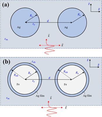
Figure 1. An electric field interacting with (a) two closely spaced 8-nm Ag spheres and (b) two closely spaced Fe@Au core–shell NPs. The core diameter was determined by the radius Rc and electrical permittivity εc , while the shell was defined by the radius Rsh and electrical permittivity εsh . εm and d represent the electrical permittivity of the surrounding media and particle distance, respectively. The directions of propagation and polarisation of the optical field are indicated.
Download figure:
Standard image High-resolution imageThe MO effects occur from a magnetic field-induced anisotropy, which manifests itself through the presence of non-symmetric, off-diagonal components of a dielectric tensor of the materials. These off-diagonal components (see equation (9)) are a result of different electronic transitions excited by left and right circularly polarised light [17]. To utilise the DDA method for these materials, the dielectric tensor in the Cartesian basis must be diagonalised by transforming it into a right-left-handed circular cylindrical coordinate system. This can be done by [17]:

where
Then, the Kuwata approximation for calculating the polarisability in equation (4),  of the sphere becomes:
where subscript u represents the diagonalised component (right, left, and z). Similarly, the matrix  and the vectors
  and
and  must be transformed into the circular cylindrical coordinate system with equation (10). Eventually, equation (5) becomes:

These allow calculation of the polarisation of each particle. Consequently, the optical absorption efficiency of a spherical core–shell nanoparticle in equation (6) can be calculated. Then, the Faraday rotation spectrum can be calculated by the relationship [17]:

where Δn is the magnitude of circular birefringence which is the difference in the refractive index of left and right circularly polarised light in the medium, λ is the wavelength of the incident light, while  and
and  are the effective diagonal and off-diagonal dielectric components in Cartesian coordinates, respectively. The dielectric constants for Fe and Ag were determined from published literature, [22] and [23], respectively. The core–shell NPs were assumed to be surrounded by a homogeneous medium of PMMA polymer (εm
= 2.25). Then, the optical absorption and MO Faraday rotation properties can be calculated using equations (6) and (13), respectively.
are the effective diagonal and off-diagonal dielectric components in Cartesian coordinates, respectively. The dielectric constants for Fe and Ag were determined from published literature, [22] and [23], respectively. The core–shell NPs were assumed to be surrounded by a homogeneous medium of PMMA polymer (εm
= 2.25). Then, the optical absorption and MO Faraday rotation properties can be calculated using equations (6) and (13), respectively.
3. Results and discussion
Initially, the range of applicability of the DDA method was examined by comparing it with the exact Mie theory for pure single spherical nanoparticles with diameters in the range of 5–50 nm. In the calculation, the k-vector of incident light was propagated in the z-direction and polarised in the x-direction (see figure 1). In this case, the particles were perpendicular to the k-vector and parallel to the polarisation direction. The DDA method was utilised to investigate light absorption in a pair of identical particles.
Figure 2 shows that for Ag spheres in water, the DDA method shows good agreement with the exact Mie absorption efficiency for very small particles. Resonance absorption peaks were observed at ∼401, ∼407 and ∼413 nm for diameters of 5, 10, and 30 nm, respectively. The most significant departure from the exact Mie theory was observed for particles larger than 50 nm in diameter. The quadrupolar mode was found in the exact Mie spectrum, which appears at a shorter wavelength compared with the dipolar mode. It was observed at a wavelength of ∼388 nm for quadrupolar peaks, whereas the dipole peak was observed at ∼401 nm. Moreover, for particle sizes in the range of 5–30 nm, a longer wavelength-shifted LSPR peak and stronger absorption efficiency are observed. Physically, due to the resonance frequency, ωp
is proportional to  where ne
is the density of the free electrons. Therefore, a smaller particle results in a lower energy mode (longer wavelength-shift).
where ne
is the density of the free electrons. Therefore, a smaller particle results in a lower energy mode (longer wavelength-shift).
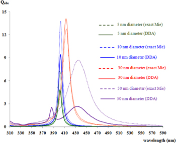
Figure 2. Comparison of DDA using Kuwata polarisability with exact Mie theory for single Ag nanoparticle absorption efficiency.
Download figure:
Standard image High-resolution imageFigure 3 presents the optical absorption activity for the two basic two-particle geometries of Ag NPs with varying Ag NPs interparticle distances ranging from 8–100 nm. A blueshift of the absorption peak position was observed with increasing interparticle distance. Resonance absorption peaks were found at ∼522, ∼448, ∼424, ∼412, ∼406, and ∼402 nm, respectively, for interparticle distances of 8, 10, 12, 15, 20, and 100 nm. The trend line of the shifted absorption peak due to LSPR excitation is also shown in the inset in figure 3(a). Still, for an interparticle distance of 20 nm, the blueshift becomes less substantial than for longer interparticle distances. Alternatively, as shown in figure 3(b), a redshift of the absorption peak position with increasing interparticle distance was observed when the polarisation direction of the incident light was perpendicular to the particle axis (y-axis). When the interparticle distance was increased from 8 nm to 10, 12, 15, 20, and 100 nm, the resonance absorption peaks shifted from ∼378 nm to ∼388, ∼394, ∼398, ∼400, and ∼402 nm, respectively. The trend line of shifted peak absorption is illustrated in the inset of figure 3(b). For a two-particle system, bringing them closer together results in a scattered field from one particle that interacts with the other (and vice versa). A response of a shift in the LSPR optical absorption peak of the Ag NPs can be observed. This phenomenon can be explained using the dipole-dipole interaction model [24–26]. LSPR can be considered analogous to a mass-and-spring model where the resonant angular frequency can be simply given by  K being the spring constant and M the total mass of conduction electrons participating in the localised surface plasmon. For the transverse mode, the polarisation direction of the incident field is perpendicular to the particle pair axis. The charge distributions act cooperatively to enhance the repulsive action of both particles, equivalent to the fields generated by neighboring spheres that are out of phase. An increased spring constant, K, should be generated. This mode produces an increased resonance frequency, ω0, or blueshift. For the longitudinal mode, in contrast, the polarisation direction of the incident field is parallel to the particle pair axis. A restoring force in the opposite direction is generated. This mode results in reducing the spring constant, K.
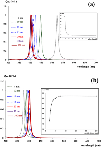
Figure 3. Absorption efficiency of two closely spaced 10-nm Ag NPs as a function of wavelength with various interparticle distances between 8–100 nm. (a) Two particle axes aligned perpendicularly to the propagation direction and parallel to linear polarised light, and (b) Two particle axes aligned perpendicularly to both propagation direction and linear polarised light. The insets in (a) and (b) show the surface plasmon peak position of isolated Ag NPs as a function of the incident wavelength. Circles and solid lines represent the calculated data and fitted curves, respectively.
Download figure:
Standard image High-resolution imageThe resonance frequency of the longitudinal mode should be therefore smaller than that of an isolated sphere. This is the source of the redshift. Figure 4 shows the optical absorption and MO Faraday rotation spectra of two closely spaced 10-nm pure Fe NPs with various interparticle distances ranging from 20–100 nm as a function of incident wavelength. In this calculation, the magnetic field is parallel to the direction of light propagation, as in equation (10), while the k-vector of incident light propagates in the z-direction and is polarised parallel to the x-axis.
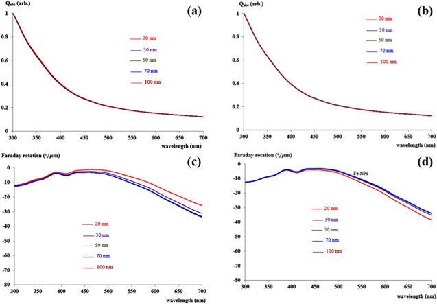
Figure 4. Calculated absorption efficiency ((a) and (b)) and MO Faraday rotation ((c) and (d)) for two closely spaced 10-nm Fe NPs as a function of wavelength with interparticle distances ranging between 20–100 nm. (a) and (c) particle axes are parallel to the polarisation direction of the incident light, whereas (b) and (d) particle axes are perpendicular to the polarisation direction of the incident light.
Download figure:
Standard image High-resolution imageFigures 4(a) and (b) show the optical absorption spectra of Fe NPs, whereas the MO Faraday rotation spectra are shown in figures 4(c) and (d) at various incident wavelengths in the visible region. In both parallel and perpendicular particle axes to the polarisation direction of the incident light, the optical absorption spectra of the unmodified Fe NPs do not show any absorption in the visible region, in agreement with experimental results [26]. Considering the MO Faraday rotation spectra in figure 4(c), when the Fe NPs are aligned on the axis that is parallel to the polarisation direction of the excited light, the Faraday rotation spectra at any incident wavelength show a larger rotation angle with increasing interparticle distance. In contrast (see figure 4(c)), it produces a smaller rotation angle with increasing interparticle distance when the longer particle axis is perpendicular to the polarisation direction of the incident light (see figure 4(d)). Therefore, it is possible to improve the optical and MO efficiency of ferromagnetic NPs to utilise them in future applications, such as in biomedicine [5–7]. Using the LSPR property induced by Ag, the optical absorption and MO Faraday rotation of Fe NPs should be enhanced and tuned in a way similar to previous reports [7, 8, 11, 27]. The significant dependence of optical and MO properties on interparticle distance and shell thickness [7, 8, 27] and the optical absorption and MO Faraday rotation spectra of two closely spaced merits are considered.
Fe@Ag core–shell NPs with various interparticle distances ranging from 20–100 nm are presented as a function of incident wavelength in figure 5. The interesting behavior of the optical absorption band was initially observed for the Fe@Ag core–shell nanocomposites (figures 5(a) and (b)). In the first case, shown in figure 5(a), the Fe@Ag core–shell NPs axis was parallel to the polarisation direction of the excited light. The absorption bands of Fe@Ag core–shell NPs show a slight blueshift. Whereas, with the alignment of the particle axis perpendicular to the polarisation direction of the excited light (see figure 5(b)), Fe@Ag core–shell NPs show a redshift of the SP resonance peak. Figures 5(c) and (d) show Faraday rotations for two Fe@Ag core–shell NPs as a function of wavelength and interparticle distances ranging from 20–100 nm. It was observed that in both parallel and perpendicular axes to the polarisation direction of the excited light, the Faraday rotation spectra were enhanced compared to that of pure Fe NPs.

Figure 5. Calculated absorption efficiencies ((a) and (b)) and Faraday rotations ((c) and (c)) for two Fe@Ag core–shell NPs as a function of wavelength with various interparticle distances from 20–100 nm. (a) and (c) particle axes are parallel to the polarisation direction of the incident light, whereas (b) and (d) particle axes are perpendicular to the polarisation direction of the incident light.
Download figure:
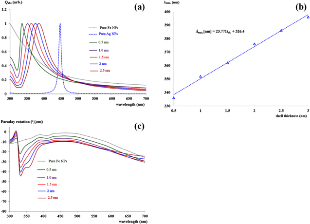
Standard image High-resolution imageFinally, for the calculations shown in figure 6, the optical absorption and MO Faraday rotation spectra of two closely spaced Fe@Ag core–shell NPs with varying Ag shell thickness as a function of incident wavelength are presented. Their diameter and interparticle distance were fixed at 10 nm and 20 nm, respectively. In the calculations, the particle axis was perpendicular to the propagation direction and parallel to the polarisation direction of light. By comparing with unmodified Fe NPs, the obtained results clearly showed strong absorption in the visible region. A redshift of the plasmon peak with increasing Ag shell thickness from 0.5 nm to 2.5 nm was observed. The LSPR peak position was found at ∼336 nm for a 0.5 nm of shell thickness and shifted to longer wavelengths of ∼352 nm, ∼362 nm, ∼376, and ∼386 nm as the shell thickness was increased to 1.0 nm, 1.5 nm, 2.0 nm, and 2.5 nm, respectively. It is clear in figure 6(b) that the LSPR peak is a function of the Ag shell thickness. It was found that the absorption peak position linearly shifts to longer wavelengths, represented by λmax = 23.771tth + 326.4, where λmax and tth are the peak position and Ag shell thickness, respectively. This redshift is due to electromagnetic coupling between the plasmon oscillations on the inner and the outer surfaces of the Ag shell [23, 25].
Figure 6. (a) Calculated absorption efficiencies as a function of wavelength, (b) LSPR position as a function of shell thickness, and (c) Faraday rotation as a function of wavelength for two Fe@Ag core–shell NPs with various Ag shell thicknesses ranging from 0.5–2.5 nm. The particle axes are parallel to the polarisation direction of the incident light.
Download figure:
Standard image High-resolution image
The calculated MO Faraday rotation spectra, shown in figure 6(c), reveal that the angle of rotation depends on the Ag shell thickness. It was found that the Faraday rotation produced by the Ag-coated Fe NPs was similar to the Faraday rotation spectrum of a pure Fe particle, except for a sharp peak that occurred at around ∼332 nm. Moreover, when increasing the Ag shell thickness from 0.5 to 2.5 nm, the angle of Faraday rotation slightly increases. The physical mechanism for the LSPR peak position shift is explained by the plasmon mode-coupling theory, developed by Prodan et al [24, 26]. In this theory, the metallic sphere plasmon from the outer surface of a metallic shell layer couples with the cavity plasmons produced from the inner metallic shell. Owing to the finite thickness of the metallic shell, the spherical plasmon and the cavity mode interact, leading to a splitting of the LSPR into two new LSPR signals, anti-bonding, and symmetric plasmons. Anti-bonding coupling results in a higher frequency mode, while bonding coupling corresponds to a lower frequency mode or a higher wavelength-shifted LSPR position. The coupling energy is proportional to a geometric parameter defined as the ratio between the inner and outer radii of the metallic shell. This means that the metallic shell thickness is associated with the interaction distance between the two modes, i.e., the strength of plasmon interaction. Therefore, these calculations are in good agreement with the plasmon mode-coupling theory. Additionally, the calculated results showed that the MO Faraday rotation can be tuned and enhanced by incorporating an Ag shell, similar to the experimental results with Fe2O3@Au NPs [7] and Fe@Au nanoparticles [27].
4. Conclusions
In summary, the optical and MO Faraday rotation properties in core–shell structured Fe@Ag NPs were numerically determined using the DDA method. This was done as a function of Ag shell thickness over the wavelength range of 400–700 nm. The dependence of optical and MO Faraday rotation properties of the particles on the interparticle distance, polarisation direction of excited light, and Ag shell thickness was described. Furthermore, the Fe@Ag NPs show an absorption band similar to that of Ag NPs, but broader. The characteristic absorption and MO Faraday rotation band can be tuned and enhanced by changing the polarisation direction of the incident light, interparticle distance, and Ag shell thickness. The increased interparticle distances lead to gradual blueshift and redshift of the absorption band, respectively, when the particle axes were aligned parallel and perpendicularly to the polarisation direction of the incident light. This is similar to the shift of the MO Faraday rotation band. Also, increases in the Ag shell thickness, when the polarisation direction of incident light is parallel to the particle axis, leads to a redshift of the absorption band. A qualitative understanding of optical absorption and MO Faraday rotation of Fe@Ag NPs is useful in optical, magnetic, and biotechnological fields of research.
Acknowledgments
This work was financially supported by the Division of Research Administration, Research and Technology Transfer Affairs, Khon Kaen University (Grant Year 2019). The author acknowledges the use of facilities and support from the Faculty of Applied Science and Engineering, Nong Khai Campus, Khon Kaen University.