

Abstract
We investigate the stability of the bi-layer Fe3O4/Fe(0 0 1) films grown epitaxially on MgO(0 0 1) substrates with the layer thickness in the range of 25–100 nm upon 1 MeV Kr+ ion irradiation. The layer structure and layer composition of the films before and after ion irradiation were studied by XRR, RBS and RBS-C techniques. The interdiffusion and intermixing was analyzed. No visible change in the RBS spectra was observed upon irradiation with ion fluence below 1015 Kr cm−2. The bi-layer structure and the stoichiometric Fe3O4 layer on the surface were well preserved after Kr+ ion irradiation at low damage levels, although the strong intermixing implied a large interfacial (FexOy) and (Fe, Mg)Oy layer respective at Fe3O4–Fe and Fe–MgO interface. The high ion fluence of 3.8 × 10¹⁶ Kr cm−2 has induced a complete oxidization of the buffer Fe layer. Under such Kr fluence, the stoichiometry of the Fe3O4 surface layer was still preserved indicating its high stability. The entire film contains FexOy -type composition at ion fluence large than 5.0 × 10¹⁶ Kr cm−2.
Export citation and abstract BibTeX RIS

Original content from this work may be used under the terms of the Creative Commons Attribution 3.0 licence. Any further distribution of this work must maintain attribution to the author(s) and the title of the work, journal citation and DOI.
1. Introduction
Iron oxides, magnetite (Fe3O4), maghemite (γ-Fe2O3), hematite (α-Fe2O3) and wüstite (FeOx), form naturally of Fe-containing rocks. They play an important role where they exist everywhere (in rocks (both on lands as well as in oceans), soils and dust in the atmosphere) and have integrated in many biological systems including the human body tissues. Magnetite (Fe3O4)—the oldest known magnetic material has been studied since the early days of science. Since the 1960s magnetite has been investigated extensively due to its high potential for technological applications in many important fields, e.g. high-density recording media and catalysis [1]. Magnetite crystallizes into a cubic inverse spinel structure and is a ferrimagnet below 858 K (TN) with a net magnetic moment of 4.1 µB per formula unit. The coexistence of Fe2+ and Fe3+ ions in the octahedral sublattice leads directly to many interesting properties, e.g. the Verwey transition around 123 K [2–4]. In recent years, magnetite has attracted again much attention, since it is referred as a half-metallic material having a predicted full spin polarization at the Fermi level and thus considered as a promising candidate for spintronic devices at room temperature utilizing the spin polarised current [5, 6]. Many attempts have been focused on determining the spin polarisation of magnetite [7, 8], on using magnetite as electrode in spin valve [9], tunnel magneto-resistance [10–12] and magnetic tunnel junctions [13, 14]. Besides, magnetite has recently exhibited its high potential for biomedical applications, such as Fe3O4 -based nanoparticles used as contrast agent for magnetic resonance imaging scanner/diagnosis [15, 16] and as drug delivers/carriers for e.g. anticancer treatments [16–18].
In the last few decades, an increasing interest is focused on the iron oxide surfaces, since they play a major role in e.g. corrosion, catalysis, spintronics and biomedicine [19–21]. In particular a large attention is paid to magnetite films due to their potential application as spin dependent transport devices. Especially, up to 72% mobile electrons were found to be polarized in Fe3O4(0 0 1)/MgO(0 0 1) films [22]. Besides, using thin films opens an exciting road for future research of surface engineering through absorption, which may permit tailoring of the interfacial spin polarization in magnetite-based spintronic devices [23]. The best understood iron oxide surface at present is probably Fe3O4(0 0 1) surface; its structure is known and the major properties are well characterised [24]. The best technique to grow Fe3O4(0 0 1) thin films is the reactive molecular beam epitaxial (MBE) deposition utilizing MgO(0 0 1) substrate [25]. For a review of surface termination and reconstruction of Fe3O4 surfaces, see references [7, 24–28].
The physical and structural properties of interfaces play a crucial role in obtaining well-orientated thin films. Not only the surface but also the interface can be performance-limiting the practical applications of magnetite. Besides, while a large effort is focusing on the magnetite film surfaces, their interfaces have been less studied. It is thus important to investigate the interfaces and their correlation to the entire-film properties. Moreover, regarding the possible technical applications, it is worth obtaining the knowledge of the stability of the magnetite films in the external conditions, such as high temperature (annealing) and ion irradiations. In fact, there is a lack of the knowledge of interdifussion and intermixing effects in magnetite films. To the best of our knowledge, there is no report on such a research for Fe3O4 thin films, except of our publications [29–31]. There existed some reports devoted to using the swift heavy ions to modify the magnetic and transport properties of magnetite films [32, 33].
The goal of the present work is to use MeV ion beams to study and modify the structure, composition and properties of magnetite films especially at the interfaces. We are interested in finding the ion fluence upon which the film structure and the Fe3O4 surface layer can be well preserved under ion irradiations. We have exploited Rutherford backscattering (RBS) and RBS-channeling (RBS-C) methods, since they allow the detection of elements in the sub-monolayer range with an atomic depth resolution typically in the nanometers range. In particular, RBS-C can provide the information about the crystalline quality (crystalinity) of the films. The main subject of our investigations are the bi-layer Fe3O4/Fe/MgO(0 0 1) films. Our results supported the earlier observations [27, 34] that by using a two-step deposition procedure, in which the Fe3O4 layer was deposited reactively on an epitaxial Fe(0 0 1) buffer layer grown epitaxially on MgO(0 0 1) substrate, we could always obtain the stoichiometric Fe3O4 on the film surface. Moreover, such a layer was found to remain stable upon thermal annealing as well as in exposing to air. However, RBS-C data revealed that the large lattice mismatch at both Fe3O4/Fe and Fe/MgO interface (of about 4%, in a comparison with 0.31% for Fe3O4/MgO one) has degraded the film crystallinity [31]. Our up-to-date investigations have been mostly carried out for very thin layers (with a layer thickness of 10–20 nm). In this work, we extend our investigations of the intermixing on the bi-layer Fe3O4/Fe/MgO(0 0 1) films with a larger film thickness (in the range of 25–150 nm) under 1 MeV Ar+ and Kr+ ion irradiation. We expect to induce a significant intermixing (i.e. to tailor the films and their interfaces) by Kr+ ions. It allows gaining a better understanding of the film stability and the interface stoichiometry and properties.
2. Experimental
We prepared and performed investigations on the following films: (1) (25 nm)Fe3O4/(25 nm)Fe /MgO(0 0 1); (2) (50 nm)Fe3O4/(50 nm)Fe/MgO(0 0 1) and (3) (100 nm)Fe3O4/(50 nm)Fe/MgO(0 0 1). For a simplicity, we used the shorten notation Fe3O4/Fe(25-25 nm), Fe3O4/Fe(50-50 nm) and Fe3O4/Fe(100-50 nm), where the nominal layer thickness values were given in the brackets. The film growth-procedure and characterization by in situ low energy electron diffraction (LEED) and conversion electron Mössbauer spectroscopy (CEMS) in a multi-chamber UHV system have been reported earlier [26, 27, 34]. We also performed similar experiments on the Fe3O4(0 0 1) films prepared in a standard reactive deposition directly on MgO substrates with similar film thickness, e.g. (25 nm)Fe3O4/MgO(0 0 1) and (50 nm)Fe3O4/MgO(0 0 1) denoted as Fe3O4(25 nm) and Fe3O4(50 nm). By analyzing and comparing the results obtained for films with either a similar layer structure but with different layer thicknesses or with a similar layer thickness but with a different layer structure, we expect to gain a deep understanding of the atomic transport process. These single-layer magnetite films possess a high crystalinity. However, Mg out-diffusion from MgO substrate into the Fe3O4 film implies that entire film or a part of the film has a spinel composition. Indeed, Mg was found to segregate to the surface for the thin film with a thickness <25 nm.
The chemical composition and layer structure of the films in the as-grown state have been determined by a combined Rutherford back-scattering (RBS) and x-ray reflectometry (XRR) analysis. The RBS spectra by using 2 MeV He+ ions at a backscattering angle of 171° were collected and evaluated at different tilt angles φ in the range of 0–45° [28]. SIMNRA simulation program was used for RBS data analysis, taking into account the electronic stopping power data by Ziegler and Biersack, Chu Yang's theory for electronic energy-loss straggling and Andersen's screening function to Rutherford cross-section [35]. XRR was performed by using a Seifert two-circle diffractometer (using a rotating anode with 40 kV and 120 mA, and a LiF monocromator and a slit system for separating the Cu-Kα1 line) with the Seifert reflectivity software for the data analysis. One of the best techniques to study the film crystalline quality (crystallinity) is the RBS-C. In our study, the RBS-C spectra (by using 1.6 MeV He+ ions and a backscattering angle of 160°) were collected and evaluated at every tilt-angle step of 0.04°. Such experiments have been performed only on selected films exhibiting a high crystallinity and channeling effect.
The ion beam mixing experiments were carried out using 1 MeV Kr+ beam with ion fluence (ϕ) in the range of 1.6 × 10¹⁵–3.8 × 10¹⁶ Kr cm−2 (some ϕ -values are listed in table 1). The sample temperature was kept at −50 °C during irradiations. Each film after each ion irradiation was analyzed by RBS. We chose such ion type, energy and ion fluence to optimize the ion beam mixing effect at the Fe3O4–MgO, Fe3O4–Fe and Fe–MgO interfaces in the investigated films with chosen layer thickness mentioned above. Prior to the experiments, all irradiation parameters have been pre-estimated by using the stopping and range of ions in matter (SRIM) simulation programs [36]. Namely, the values for electronic energy loss (Se), nuclear energy loss (Sn) and the range of ion (Rp) are found to be 1.01 keV nm−1, 1.47 eV nm−1 and 334 nm for Fe3O4, respectively. For Fe, the values Se, Sn and Rp are 1.36 keV nm−1, 1.99 eV nm−1 and 241 nm, respectively. For both materials, Se and Sn is in the same magnitude and Rp is larger than the film thickness. Such ion fluences used in our experiments produced low levels of irradiation damage with evaluated displacement-per-atom (dpa) in the range of 0.00007–0.0017. The results of XRR and RBS indicate that the initial composition and thickness of the films remain unchanged after irradiation with ϕ < 1015 Kr cm−2. Using Kr+ ions, for obtaining a similar intermixing level, the irradiate time would be much shorter than Ar+ ions and thus we could avoid the contamination to the films (since the pressure of the standard irradiated chamber is maintained at only around 10−6 mbar).
Table 1. Selected results showing the effect of 1 MeV Kr+ ion irradiation on bi-layer Fe3O4/Fe/MgO(0 0 1) films (denoted by the nominal layer-thickness). d1 and d2 are respectively the estimated layer thickness of the surface Fe3O4 layer and the Fe buffer layer, d12 is the mixed FexOy layer at the Fe3O4–Fe interface, d1s and d2s are respectively the (commonly-denoted) interfacial (Fe, Mg)Oy layer between the film and the MgO substrate (see text). The relative decrease of the layer thickness is indicated by the ratio between the layer thickness before (in the as-grown state) and after irradiation (dKr): R(Fe3O4) = dKr/d1, R(Fe) = dKr/d2, respectively for the Fe3O4 and Fe layer. The results for single-layer Fe3O4/MgO(0 0 1) film are included for a comparison.
| Film (norminal thickness) | ϕ × 1015 (ions cm−2) | Fe3O4 d1 (nm) | FexOy d12 (nm) | Fe d2 (nm) | (Fe, Mg)Oy d1s/d2s (nm) | R(Fe3O4) (dKr/d1) (%) | R(Fe) (dKr/d2) (%) |
|---|---|---|---|---|---|---|---|
| Fe3O4 (50 nm) | As-grown | 50 | 0 | 0 | 3 | ||
| 8.4 (Kr3) | 0 | 0 | 0 | 53 | 0 | ||
| Fe3O4/Fe(25-25 nm) | As-grown | 28 | 0 | 22 | 5 | ||
| 8.4 (Kr3) | 24 | 9 | 16 | 30 | 86 | 73 | |
| Fe3O4/Fe(50-50 nm) | As-grown | 59 | 0 | 36 | 5 | ||
| 16 (Kr2) | 33 | 25 | 18 | 27 | 56 | 50 | |
| 38 (Kr4) | 12 | 65 | 0 | 100 | 20 | 0 | |
| Fe3O4/Fe(100-50 nm) | As-grown | 112 | 0 | 36 | 5 | ||
| 19 (Kr4) | 71 | 47 | 17 | 85 | 63 | 47 | |
The RBS, RBS-C and irradiation experiments were performed at the Institute of Nuclear Physics of the Johann von Goethe University in Frankfurt/Main (IKF-Frankfurt). We also used the second RBS equipment5 with 1.7 MeV He+ ions from a Tandetron accelerator at a scattering angle 170° and the detector out-of-plane arrangement. The sample can be rotated around the φ- and θ-axis in the small range of angles enabling to visualize the image scan of the planar channels and indicate the axial one in order to find some aligned RBS spectra. With such an arrangement, we could perform additional investigations on selected irradiated films for a structural analysis focusing on the changes that occurred after Kr+ ion irradiation.
3. Results and discussions
Each film was irradiated 1, 2, 3 or 4 times marked respectively as Kr1, Kr2, Kr3 and Kr4 (given in table 1 and in the figures), with the ion fluences in the range of 1.6 × 10¹⁵–1.9 × 10¹⁶ ions cm−2 for Fe3O4/Fe(25-25 nm) and Fe3O4/Fe(100-50 nm), whereas for Fe3O4/Fe(50-50 nm) film we used higher ion influences in the range of 6.7 × 10¹⁵–3.8 × 10¹⁶ ions cm−2 (Kr4). Kr+ irradiations with similar ion fluencies were performed on two single-layer film Fe3O4(25 nm) and Fe3O4/Fe(50 nm). The layer-thickness and composition of different layers of films in the as-grown state and after Kr+ ion radiation (by different ion fluencies) estimated from RBS data analysis are given in table 1. We present only selected data revealing a visible effect of intermixing. In general, irradiations of the magnetite films by 1 MeV Kr+ ions induce a strong Fe–Mg intermixing leading to a large change in the layer composition and thickness and especially a formation of large interface zones. We present in figure 1 the comparison of RBS spectra in the as-grown state and after Kr+ ion irradiation for Fe3O4/Fe(50-50 nm) film, for which the ion beam mixing effect is most visible to eyes. We notice here that, not only single-layer magnetite film, but also bi-layer Fe3O4 films exhibited a strong channeling effect set at untilted angle (φ = 0°) observed even if by means of a standard RBS apparatus [37], when it happened that the incoming ion beam could go forwards along the channels formed along the main crystallographic (0 0 1) direction of magnetite, implying a large decrease of the backscattered signal in the RBS spectrum. For ensuring the randomness, most of RBS spectra were collected at tilted angle φ = 10°. The RBS spectra of the as-grown film (figure 1) revealed a large Fe peak, a visible O peak (OL1, from the (first) Fe3O4 surface layer (L1)) on a high background consisted of O step-edge (Osub.) and Mg edge (Mgsub.) from MgO substrate. The Fe peak is indeed consisted of a shoulder (FeL1) at the right-hand side of a Fe peak (the maximum, (FeL2)) attributed to the Fe signal respectively from the Fe3O4 layer (with an Fe content (~43%)) and from the Fe buffer layer (the second layer (L2) contained of 100% Fe). Since both layers consisted of Fe, the (backscattered) Fe signals are always overlapped. Increasing the thickness of the metallic Fe buffer layer would lead to their separation (distinction) in some extent. Moreover, the existence of such Fe layer would lead to a separation between the O signal from the Fe3O4 film (OL1) and the large O signal (Osub) from MgO substrate. Our investigations have revealed that the minimal value for the Fe layer thickness should be 25 nm for obtaining such a separation, e.g. we observed a small but visible O peak in the RBS spectrum of Fe3O4/Fe(25-25 nm) film. Increasing the thickness of the Fe3O4 layer certainly would lead to an enhancement of the OL1 signal and FeL1 signal revealed by e.g. an increase of the width of the O-peak and Fe-shoulder, as observed for Fe3O4/Fe(100-50 nm) film. We remind here again that by using the bi-layer structure, we could ensure to get the stoichiometric Fe3O4 layer on the film surface. In fact, the onset of Mg segregation was found at 670 K [38] which largely enhanced at 700 K [39]. Any post annealing (at 800 K in our case) certainly promoted the Mg out-diffusion. Indeed, the Fe/Mg interdiffusion was found upon annealing at even a lower temperature of 600 K [40]. By increasing the Fe3O4 layer thickness, we could be able to obtain a stoichiometric Fe3O4 layer for single-layer films, when no magnesium segregation was found in the topmost surface layer, although Mg out-diffusion produced an interfacial spinel-type (Fe1−xMgx)3O4 layer at the film-substrate interface. The high guarantee of the stoichiometric Fe3O4 film was obtained in the case of the bi-layer films, when Fe layer blocks Mg diffusion into the Fe3O4 surface layer. The RBS data analysis provided the layer-thickness of (59–36 nm) for Fe3O4/Fe(50-50 nm) film, i.e. with a thicker Fe3O4 layer and a thinner Fe layer. Morever, a wüstite-type (FeyMg1−y)xO layer with a thickness of ~5 nm was formed at the Fe–MgO interface. In our previous study [36], we found out that, using a much shorter deposition time of the Fe3O4 layer and without using the post annealing, we were able to obtain the films with the Fe buffer layer with a thickness value close to the nominal one. The results gave a good proof that the top and bottom part of the Fe layer was oxidized during the film-growth. We notice here that SIMNRA analysis provides two different layers (spinel-type (Fe1−xMgx)3O4 and wüstite-type (FeyMg1−y)xO layer) at the film-substrate interface. However, for a simplicity, in table 1 as well as figures, we use a common (Fe, Mg)Oy formula for addressing both interfacial layers since they consist of Fe, Mg and O. The only difference is the different composition of each element in the layer. The first irradiation (Kr1) with the ion fluence of 6.7 × 10¹⁵ ions cm−2 already induced a very strong mixing leading to a formation of the FexOy layer (the mixing of Fe3O4 and Fe one) at the Fe3O4–Fe interface and enhancement of the (Fe, Mg)Ox layer (i.e. an increase of layer-thickness and Fe-content) at the Fe–MgO interface. Further irradiations implied much larger changes revealed by e.g. a much enhanced non-zero Fe–Mg background. Our data analysis indicated that, despite a large decreasing in the layer thickness, the bi-layer films still consisted of the pure Fe3O4-pure Fe layer structure after Kr3 irradiation (of 2.8 × 10¹⁶ ions cm−2). The pure Fe layer was found to disappear completely only after the fourth irradiation (Kr4) with the ion influence of 3.8 × 10¹⁶ ions cm−2. In other words, such the Fe layer was oxidized completely forming the FexOy layer, as a consequence of intermixing. The crucial is that the stoichiometric Fe3O4 is well-preserved at this high ion fluence. For a clear vision of the Kr+ ion irradiation effect, we have also included into figure 1 the comparison of the Fe signals and the non-zero background between Fe peak and Mg edge in an enlarged scale.
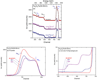
Figure 1. The random (markers) and simulated (solid lines) RBS spectra of Fe3O4/Fe(50-50 nm) film grown on MgO(0 0 1) substrate after irradiations by 1 MeV Kr+ ion beam. Osub. and Mgsub. Marked the O- and Mg-signal from MgO substrate. OL1, FeL1 and FeL2 denoted the O- and Fe-signal from the (first) surface Fe3O4 layer and (second) Fe layer, respectively. For a clear view of ion beam mixing effect, we showed the full RBS spectra (both data and simulated ones) in a comparison with that in the as-grown state (a), the enlarged Fe peaks (b) and Fe–Mg background (c) with only simulated spectra for guiding of the eyes.
Download figure:
Standard image High-resolution imageThe bi-layer Fe3O4/Fe(25-25 nm) film exhibits a channeling effect, while no clear channeling effect was observed for bi-layer films with a total film thickness >50 nm. The normalized angular yield curve (with respect to the maximal backscattered yield of the random spectra (the channeling yield curve)) obtained from RBS-C experiments for Fe in the film for Fe3O4/Fe(25-25 nm) film was shown in figure 2. For a comparison, we included in the same figure the results for the single-layer film with a layer thickness of 10 nm [30] as well as MgO substrate. The MgO substrate exhibited a perfect crystal quality indicating by a small value of the minimum yield and the full width at half maximum (FWHM) for Mg, χmin(Mg) ~ 2% and ψ1/2(Mg) = 1.5°, respectively. For the 10 nm-thick single-layer magnetite film, a high crystallinity was exhibited with χmin(Fe) ~ 20% and ψ1/2(Fe) = 1.9° (for Fe in the film). The Fe3O4/Fe(25-25 nm) film has revealed one deep minimum (χmin(Fe) = 31%, ψ1/2(Fe) = 1.4°) at a normalized tilted angle φ = 0° and one minimum-shoulder feature (χmin(Fe) = 75%) attributed to the channeling respectively through the surface Fe3O4 layer and the Fe film beneath the surface layer. The difference in the angle between the two minima in the channeling yield curve is 2 degrees, attributed to the small difference in the orientation between the Fe atomic rows in the Fe layer and in the Fe3O4 layer. For bi-layer films with thicker thickness, the large lattice mismatch at both two interfaces (Fe3O4–Fe and Fe–MgO one), the formation of the interfacial layers, the displacements of the Fe rows etc have certainly led to a lowering of the crystallinity of the entire films, despite that each Fe3O4 and Fe layer can possess good atomic arrangements (i.e. each layer can exhibit a channeling effect).
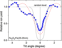
Figure 2. The channeling yield curve (the normalized angular yield curve) of Fe with respect to the [0 0 1] direction of the bi-layer Fe3O4/Fe(25-25 nm) film revealing two anomalies related to the channeling effect of the Fe3O4 film (deep minimum) and of the Fe film (minimum-shoulder feature). For a comparison, we show the channeling for Fe in a single-layer film with a layer thickness of 10 nm [28] (the red-colored dashed line) exhibiting only a single minimum and that for Mg in MgO substrate (the black-colored dashed line).
Download figure:
Standard image High-resolution imageThe absolute values of the layer-thickness and density were determined from XRR measurements. In general, a good agreement for the layer thickness was obtained between RBS and XRR results. In all cases, the densities of the magnetite layers and Fe layers are found to be respectively ρ (F3O4) = 5.2–5.4 g cm−3, ρ (Fe) = 7.5–7.9 g cm−3, similar to those of the bulk density (5.21 g cm−3 and 7.87 g cm−3 for Fe3O4 and Fe, respectively), confirming the good stoichiometry of the films. We show in figure 3 the XRR results performed on Fe3O4/Fe(25-25 nm) and Fe3O4/Fe(50-50 nm) film. In the case of Fe3O4/Fe(25-25 nm) film, the layer thickness provided from the XRR analysis was in a reasonably good agreement with that of RBS one. However, two Fe layers with the same mass density but with different roughness were revealed. The Fe layer onto MgO substrate is very rough (with the estimated surface roughness of r = 4 nm), while that beneath the Fe3O4 layer is quite smooth (r = 0.6 nm). We attributed such the large surface roughness to e.g. the large lattice mismatch between Fe and MgO (4%) during the first phase of Fe layer growth. Surprisingly, such the large lattice mismatch did not imply any roughness at the Fe3O4–Fe border. A sharp Fe3O4–Fe border line (no interface) was observed for Fe3O4/Fe(25-25 nm) film. For both Fe3O4/Fe(50-50 nm) and Fe3O4/Fe(100-50 nm) films, i.e. when the film-deposition time is twice or longer, XRR results revealed a thin interfacial layer (3–5 nm) between Fe3O4 and Fe layer with an estimated density of 6.0–6.2 g cm−3. It is certainly attributed to a mixed Fe3O4–Fe layer (or FexOy layer). The XRR measurements would not reveal e.g. the wüstite-type (FeyMg1−y)xO layer at the film-substrate interface, since the density of such (mixed) layers was similar to that of MgO substrate (3.58 g cm−3).
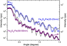
Figure 3. X-ray reflectivity (XRR) data (markers) and fits (lines) for Fe3O4/Fe(25-25 nm) and Fe3O4/Fe(50-50 nm) film in the as-grown state.
Download figure:
Standard image High-resolution imageWe notice here that, despite of the fact that we could observe visible features in the RBS spectra, we should be careful in getting a reliable analysis in nm range, i.e. in the range of the depth resolution of a standard RBS method. On the other hand, both RBS and XRR results provided no evidence for an excess Fe within the Fe3O4 or for a stoichiometry gradient in the as-grown films. One might expect that growing the Fe3O4 film on an Fe buffer layer would lead to a film with excess interstitial Fe, but it is certainly not our case (for thick films). The excess Fe was found to exist, but only in a thin interfacial layer (3–5 nm) between Fe3O4 and Fe layer, and not in entire Fe3O4 film. Each bi-layer film indeed consists of the stoichiometric Fe3O4 and Fe layer. We found even no interface (within RBS and XRR resolution) in the Fe3O4/Fe(25-25 nm) film (as mentioned above).
Due to the formation of the mixed layers and large interface zone as a consequence of ion-induced intermixing, the films have no longer any clear layer-layer separation between different layers. Namely, Fe, O and Mg are present everywhere. (Mg is absent only in the stoichiometric Fe3O4 layer on the surface of the bi-layer films). The only difference between different layers or sub-layers is the difference in the element composition. However, the difference in the mass density of those mixed layers is small. Thus we could not obtain any reliable XRR results for irradiated films. Besides, the crystallinity is low and we were unable to obtain any reliable RBS-C results.
The pure Fe3O4 layer and the bi-layer structure of other films were found to survive under Kr+ ion irradiation, although the layer thickness decreases largely (see table 1). The damage together with a large layer roughness, inhomogeneous mixed elements in the layer and between different layers, etc would certainly be the source of a large uncertainty of our RBS data-analysis for irradiated films. In other words, one should not trust completely the values themselves, but rather the meaning which they brought (the possible changes). Our investigations indicated that RBS measurements and data analysis provided a very clear picture of the ion mixing effect. We show in figure 4 the RBS spectra of three irradiated films after third or fourth irradiation. For a comparison, we show the normalized spectra and also the data for the single-layer Fe3O4(50 nm) film. For the Fe3O4(50 nm) as well as Fe3O4/Fe(25-25 nm) film, only one (overlapped) Fe peak was revealed, the ion beam mixing after the third irradiation was exhibited by a large decrease of the Fe peak intensity and a visible non-zero background between the Fe peak and Mg edge. For Fe3O4/Fe(100-50 nm) film, the distinguished Fe peak (maximum) and the wide shoulder feature were still observed after the fourth irradiation, indicating that the main bi-layer structure was still existed, despite that the layer thickness decreases largely. Namely, the layer-thickness remains as 63% and 69% respectively for Fe3O4 and Fe layer with respect to 100% as that in the as-grown state (table 1). No such distinguished Fe peak was observed for Fe3O4/Fe(50-50 nm) after the fourth irradiation by a twice larger ion influence, since the pure Fe layer was no longer existed (or in other words the Fe layer was oxidized completely). The layer-thickness of Fe3O4 layer remains as 20%, while a value of 0% was found for Fe layer. For both those two films, a much larger non-zero background between the Fe peak and Mg edge was observed. Some small step-decreases were revealed attributed to a small deviation of element composition in different sub-layers (i.e. Fe redistribution into the MgO depth).

Figure 4. Ion-induced intermixing under 1 MeV Kr+ ion irradiation observed in the RBS spectra of different films (for guiding eyes, we show only the simulated spectra.) In all cases, non-zero background was revealed, shown in an enlarged scale in the inset. An Fe peak with a large intensity was revealed for the film (4), while no such distinguished Fe peak was observed for the film (3) under irradiation with a twice larger ion fluence.
Download figure:
Standard image High-resolution imageRBS and XRR data analysis for Fe3O4/Fe(100-50 nm) after (Kr4) irradiation provided three distinguished layers: Fe3O4 layer on the surface, the Fe layer and in between those two pure layers is the FexOy layer (table 1). Since each layer has a large enough layer-thickness, we decided to perform additional RBS experiments with titled samples using a different RBS equipment7 on this irradiated film to look for a possible aligned RBS spectrum, despite of the fact that the film certainly has a low crystallinity. The results were shown in figure 5. The random RBS spectrum has revealed similar features as that collected by using the first RBS equipment revealing only Fe peak and a wide shoulder at the right hand side. By turning the sample, at a certain proper titled angle, we have observed a channeling effect through different layers. Namely, we obtained the aligned RBS spectrum exhibiting three peaks structure attributed to the three identified layers.
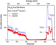
Figure 5. The random and aligned RBS spectra of irradiated Fe3O4/Fe(100-50 nm) film by 1MeV Kr+ ions after the fourth irradiation. The aligned spectrum revealed three peaks structure attributed respectively to Fe3O4, FexOy and Fe layer. The RBS experiments were performed with 1.7 MeV He+ ion beam and the scattering angle of 170° and with the out-of-plane detector6.
Download figure:
Standard image High-resolution imageIt is worth simulating the damage depth profiles induced by Kr+ ion irradiations. An energetic ion penetrating through a Fe3O4 and/or Fe generates vacancies in the Fe and O sublattices as well as Fe and O interstitials. The vacancies depth distribution in the particular layers can be evaluated by the Monte Carlo simulation of the ion interaction with matter using SRIM code [35]. Despite of the fact that SRIM theoretical calculations of atomic displacements take into account only ballistic processes and completely neglect dynamic ones as well as do not take into account crystallinity, SRIM simulations show the general trend and the damage propagation through the layers. In figure 6 we presented SRIM simulations with the full damage cascade for 1 MeV Kr+ ions in Fe3O4/Fe(100-50 nm) film revealing the Fe, O and Mg vacancies in the particular layers. We used the displacements energy in Kinchin–Peace model of 24 eV, 28 eV and 25 eV for Fe, O and Mg, respectively. The projected range of ion (Rp) is of 334 nm and the standard deviation is of about 96 nm. Fe and O vacancies illustrate the equal propagation of defects via Fe and O atoms knocking in the Fe3O4 matrix. We notice an increase of vacancies in the Fe layer attributed to a higher density of this layer (i.e. to an increase of the number of atoms per length of the ion trajectory and of energy stopping). Besides, the Fe vacancies depth profile in Fe buffer layer has the same shape as that we observed in the RBS spectrum in figure 5, taking into account the fact that SRIM included two layers only (Fe3O4(100 nm) and Fe(50 nm)) and not FexOy intermixed layer created during the irradiation. The O and Fe vacancies depth profile in the first layer has in fact the same shape, thus are not recognizable in the figure 5, but it can be deduced from the total vacancies depth profiles, that the total number of vacancies is about twice higher as the sum of Fe and O vacancies.
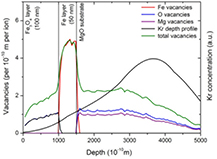
Figure 6. SRIM simulation of the damages in Fe3O4/Fe(100-50 nm) film on MgO substrate induced by 1 MeV Kr+ ions. Fe, O, Mg and total vacancies depth profiles are presented simultaneously with the Kr predicted implantation depth profile.
Download figure:
Standard image High-resolution imageFor a clear illustration of the ion beam mixing effect, i.e. the change in the composition and thickness of the layers, we show in figure 7 the film diagram before and after (selected) irradiations. We draw the layer thickness in a millimeter scale while keeping the same proportional portion with respect to the values estimated from SIMNRA in nm for different layers of the films (see table 1). The original separation (i.e. in the as-grown state) between the film and MgO substrate is indicated by the solid lines. Different colours indicate different layer compositions. In order to have a good view regarding the change of the layer thickness and composition, we show only the main layers. For instance, we presented only one mixed FexOy layer, although the RBS data analysis provided that such a layer consisted of several sub-layers with a small deviation of x- and/or y- component. Besides, we used the straight lines to show the real values of the estimated layer thickness of the mixed layers deeply into the MgO substrate, while for a large layer-thickness of the mixed layers we show the reduced thickness presented by curved lines. It shows clearly that the pure Fe3O4 layer in all investigated bi-layer films were well-preserved, while that for the single layer films could not survived under 1 MeV Kr+ ion irradiations.
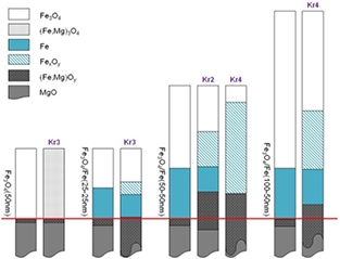
Figure 7. Illustration of ion-induced intermixing in bi-layer magnetite films by 1 MeV Kr+ ion beam. The results for the single-layer film were included for a comparison. The layer thicknesses are drawn in the mm scale, but with the same proportion to the value in nm given in table 1. The original separation between the film and MgO substrate is shown by the red-colored solid line. The straight lines were used for the real values of the estimated layer thickness. The curved lines demonstrate the reduced thickness of a large mixed layers deeply into the MgO substrate.
Download figure:
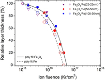
Standard image High-resolution imageThe dependence of the relative changes of the layer thickness (in %) with increasing Kr fluence is shown in figure 8. As we mentioned earlier, irradiation with Kr fluence below 1015 Kr cm−2 did not lead to any visible change in the RBS spectra. However, the relative layer thickness was found to decrease rapidly upon Kr fluence higher than 1016 Kr cm−2. The ion fluence upon which the Fe buffer layer disappeared determined experimentally was 3.8 × 10¹⁶ Kr cm−2. From a polynomial fits through the data points, the stoichiometry of the surface Fe3O4 layer is expected to be destroyed (i.e. the composition is changed into FexOy, i.e. x ≠ 3, y ≠ 4) upon irradiation with a larger fluence >5.0 × 10¹⁶ Kr cm−2.
Figure 8. Relative change (%) of the layer thickness for three bi-layer magnetite films as a function of Kr fluence upon 1 MeV Kr+ ion irradiation used in our experiments. The full and open markers indicate the change of the surface Fe3O4 and buffer Fe layer, respectively. The solid and dash line show the polynomial fit of the experimental data.
Download figure:
Standard image High-resolution image
4. Conclusions
Our investigations showed that the stoichiometry of the Fe3O4 layer on the surface of the bi-layer film (the magnetite-on-Fe film) is well preserved under 1 MeV Kr+ ion irradiation at a large ion fluence ϕ = 3.8 × 10¹⁶ ions cm−2, indicating a high stability of magnetite layer in external conditions such as Kr+ ion irradiation. This information is crucial for using the magnetite-based devices in spintronics. Besides, the bi-layer structure (Fe3O4/Fe film-structure) was also preserved under ion irradiation with lower ion fluencies.
1 MeV Kr+ ion irradiation has induced a large interfacial zone resulting in a more than double thickness of the films. It indicates a possibility of using the high-energy ion beam in controlled experiments for tailoring of the magnetite films and their interface engineering to obtain the layers or the interfaces with required thickness and desired properties for the practical applications.
Acknowledgments
The magnetite thin films were prepared within the scope of cooperation with Prof J Korecki (AGH Kraków). We highly acknowledge the fruitful cooperation with RBS group in the Institute of Nuclear Physics of the University Frankfurt/Main during performing RBS and RBS-C experiments.