

Abstract
The BiFe1−xNixO3 (x = 0, 0.05, 0.1, 0.2, and 0.3) nanoparticles were prepared by a simple solution method. Their nanostructures were characterized by x-ray diffraction (XRD), scanning electron microscopy (SEM), transmission electron microscopy (TEM), x-ray absorption spectroscopy (XAS) and gas absorption techniques. The magnetic properties of the nanoparticles were studied by using a vibrating sample magnetometer (VSM). The increasing of Ni content with decreasing of crystallize size can improve magnetization. Moreover, the samples were fabricated as electrodes to study the electrochemical properties by cyclic voltammetry (CV), galvanostatic charge-discharge (GCD) and electrochemical impedance spectroscopy (EIS). The high specific capacitances of the electrodes are in the range of 193–514 F g−1. Although the increasing of the Ni content leads to decreasing of the specific capacitances, the 5% Ni-doped BiFeO3 can improve the capacity retention (82%) after 500 cycles at 10 A g−1.
Export citation and abstract BibTeX RIS

Original content from this work may be used under the terms of the Creative Commons Attribution 3.0 licence. Any further distribution of this work must maintain attribution to the author(s) and the title of the work, journal citation and DOI.
1. Introduction
Perovskite BiFeO3 (BFO) is a popular multiferroic material due to the co-existence of ferroelectricity and ferromagnetism [1, 2], its potential applications in data storage, sensors, and spintronic devices, as well as the interesting physics involved in understanding their properties [1, 3]. The multiferroic material exhibits spontaneous polarization and antiferromagnetism ordering with a high ferroelectric Curie temperature Tc of ~1103 K and an antiferromagnetic Neel TN temperature of ~643 K [1, 3]. Several studies have been devoted to the improving of the multiferroic properties of BiFeO3 with reduction of size of nanoscale on improvement of the magnetic properties of BiFeO3 through cation substitution realized by B-site (Fe-site) doping, such as nonmagnetic metal ion of Cu [4] or magnetic ions of Co [5] and Ni [6–8] enhanced magnetization. The magnetization suppression in bulk BiFeO3 occurs due to its spin spiral structure. Size-dependent magnetic properties of BiFeO3 are strongly correlated with decreasing nanoparticle size below cycloidal spin wavelength of ~62 nm and uncompensated spin at the surface [9]. (Nd, Ni) co-doped BiFeO3 can improve magnetization due to the suppression of spin cycloid structure of the particle size and the decrease in crystallite size with increasing of Ni content [6]. Thus, The Ni atom can be considered as a candidate for the enhancement of magnetic properties due to the fact that its radius ion is similar for substitution which may be attributed to the size effect of nanostructures and their magnetic properties.
Moreover, BiFeO3-based nanomaterials have been used as potential active electrode materials for electrochemical supercapacitors which have attracted great attention over the past few decades due to their having higher power density and longer life cycle than batteries and higher energy density than conventional dielectric capacitors, which suggest potential applications in electric vehicles, power sources, portable electronics, and other devices [10]. Generally, electrochemical capacitors are classified into two types on the basis of the charge storage mechanism used such as (1) electric double-layer capacitors (EDLCs), which depend on the non-Faradic charge separation at the interface between an electrode (such as carbon materials with very high surface area) and an electrolyte [11, 12]; and (2) pseudocapacitors, which depend on electron transfer that occurs near the electrode/electrolyte interface through a fast reversible redox reaction (such as oxide materials) [11, 13]. Nowadays, transition metal oxides such as TiO2, MnO2, NiO, Co2O3, MoO3, V2O5, and Fe2O3 are studied for supercapacitor applications due to their high pseudocapacitance, which have a higher capacitance performance than normal electric double-layer capacitors, low cost, and environmental friendliness [14, 15]. In particular, the high specific capacitance and high reliability of hydrous RuO2 has been found to be very high. However, the restrictive price and toxicity of RuO2 have limited practical use [15]. Many research studies have tried to improve the electrochemical performance by fabrication of various forms of BiFeO3 as electrode materials, such as perovskite BiFeO3 thin-film electrodes [16], BFeO3 nanorods on porous anodized alumina (AAO) templates [17] as well as Cu-doped BiFeO3 nanoparticles electrodes [4]. The BiFeO3 nanoparticles showed higher specific capacitance (513.5 F g−1) than BiFeO3 thin-film (81 F g−1) and BFeO3 nanorods (450 F g−1). Moreover, BiFe0.95Cu0.05O3 can improve the specific capacitance (568.13 F g−1) and the capacity retention (77.13%) after 500 cycles due to pore size distribution.
These factors explain the motivation for this work. For the above reasons, we chose Ni metal ion as the substituent to study and to clearly clarify the mechanisms underlying the effects of Ni addition to the magnetic properties of BiFeO3 nanoparticles. Additionally, the Ni-doped BiFeO3 nanoparticles were used as candidates for electrode materials for electrochemical supercapacitors and the effects on the electrochemical performances of Ni-doped BiFeO3 were studied.
2. Materials and methods
2.1. Synthesis of BiFe1−xNixO3 nanoparticles
BiFe1−xNixO3 (x = 0, 0.05, 0.1, 0.2,n and 0.3) nanoparticles were synthesized by a simple solution method. The precursor solution was prepared by dissolving 15 mmol each of Bismuth (III) nitrate pentahydrate [Bi(NO3)35H2O, 99.9%, Kento], iron(III) nitrate enneahydrate [Fe(No3)2 · 9H2O, 99.9%, Kento] in ethylene glycol solution for 2 h. Then Ni(II) nitrate hexahydrate [Ni(NO3)2 · 6H2O, 99.9%, Kento] was added to the solution and dissolved for 2 h and then dried at 100 °C on a hotplate with stirring for 48 h. Next, the dried precursors were calcined at 600 °C for 3 h at a heating rate of 10 °C min−1, leached in 20% diluted HNO3 and deionized water seven to ten times and dried in an oven at 100 °C.
2.2. Particle characterization
The XRD patterns of the Ni-doped BiFeO3 nanoparticles were investigated by using XRD (D2 Advance Bruker) analysis with Cu Kα at λ = 0.15406 nm. The Rietveld refinement technique with TOPAS software was used to investigate the crystal structure. For the space groups, the space groups of R3c (JCPDS No. 86-1518) for the rhombohedral phase, Pbam (JCPDS No. 72-1832) for the orthorhombic phase and Fd3m (ICSD No. 40040) for the cubic phase were used. The crystallite size of the nanocrystalline samples was measured from the line broadening analysis based on the Debye-Scherer equation [18]
where D is the crystallite size (nm), λ is the x-ray wavelength, θ is the diffraction angle, and β is the full width at half maximum (FWHM) intensity. Moreover, the particle sizes were calculated from the surface area of BiFe1−xNixO3 nanoparticles using the following equation [19–21]

where DBET is the average particle size (nm), ρ is the crystallographic density (g cm−3) and A is the specific surface area according to the BET isotherm (m2 g−1). The particle morphology was examined by scanning electron microscopy (SEM; JSM-7800F) and transmission electron microscopy (TEM; FEI TECNAI G2 20). In order to determine the valence state of Ni and Fe, x-ray absorption near edge spectra (XANES) of Ni and Fe K-edge spectra were recorded in the fluorescence and transmission modes, respectively at the SUT-NANOTEC-SLRI XAS Beamline (BL 5.2) (electron energy, 1.2 GeV; bending magnet; beam current, 80–150 mA; (1.1–1.7) × 1011 photon s−1) at the Synchrotron Light Research Institute (SLRI), Nakhon Ratchasima, Thailand. The normalized XANES data were processed and analyzed using ATHENA software which included an IFEFFIT package [22, 23]. The surface area (Sp) and pore characterizations were obtained from N2 adsorption technique by BEL SORP-miniII after degassing at 80 °C for 18 h. The total specific area (SBET) and total pore volume (Vpore) and pore size distribution were investigated by the Brunauer–Emmett–Teller (BET) and Barret–Joyner–Halenda (BJH) methods, respectively, with the same equipment.
2.3. Measurements of magnetic properties
The magnetic properties of the nanoparticles were measured using the vibrating sample magnetometer (VSM) option in the Quantum Design Versalab instrument. The hysteresis loops were collected in magnetic fields from 30 kOe to −30 kOe at various temperatures from 350 K to 50 K. Zero-field cooled (ZFC) and field-cooled (FC) temperature-dependent magnetization curves were measured with applied magnetic fields of 500 Oe from 350 to 50 K.
2.4. Preparation of electrodes and electrochemical measurements
The working electrodes were prepared by mixing the Ni-doped nanoparticles, acetylene black and a polyvinylidene difluoride (PVDF) binder (weight ratio of 80:10:10) using n-methyl-2 pyrrolidinone (NMP) as a solvent to form a slurry on a nickle foam current collector. Then, the electrode was dried at 70 °C for 12 h and pressed at 20 MPa, respectively. Each working electrode contained about 3 mg of electroactive material and the area of coating was about 1 cm2. The electrochemical measurement was employed to explore the electrodes for electrochemical supercapacitor application with 6 M KOH aqueous electrolyte in a three-electrode system on Metrohm Autolab PGSTAT 302N, which consists of the active materials, a platinum wire and Ag/AgCl electrodes as working, counter, and reference electrodes, respectively. The electrochemical impedance spectroscopy (EIS) test was collected with a frequency range of 0.1 Hz–100 kHz. Cyclic voltammetry (CV) was performed at a potential window in the range of −1.2 V to 0.3 V and different scan rates of 5, 10, 20, 40, 60, 80, and 100 mV s−1 were applied. The enclosed area of the CV curve can be used to estimate the electrochemical specific capacitance (CCV) using the following equation [24]
where I is the response current density discharge current (A cm−2), υ is the potential scan rate (mV s−1), m is the mass of the electroactive materials in the electrodes (g cm−2), and ΔV is the potential window (V).
For the galvanostatic charge-discharge (GCD) measurements, the GCD curves at different current densities of 1, 2, 5, 10, 15, and 20 A g−1 were tested to investigate the electrochemical performances of the Ni-doped BiFeO3 electrodes. The specific capacitance (CGCD), was calculated using the following equation [24]

where i is the discharged current (A), ΔV is the potential window (V), and Δt is the discharge time (s).
3. Results and discussion
3.1. Structural analysis
The XRD patterns of the BiFe1−xNixO3 (x = 0, 0.05, 0.1, 0.2, and 0.3) nanoparticles calcined at 600 °C for 3 h are shown in figure 1. It can be seen that all the samples are found in the main phase of BiFeO3 revealing the rhombohedral structure with the space group R3c. Small impurity peaks of Bi2Fe4O9 (in x = 0, x = 0.05 and x = 0.1 samples) and NiFe2O4 (in x = 0.2 and x = 0.3 samples) were observed. The development of the spinel phase of NiFe2O4 helped to prevent the formation of the Bi2Fe4O9 phase.

Figure 1. XRD patterns of BiFe1−xNixO3 (x = 0, 0.05, 0.1, 0.2, and 0.3) nanoparticles.
Download figure:
Standard image High-resolution imageA shift in the peak position was observed towards the lower angles in the Ni-doped samples due to the higher ionic radius of Ni2+ (0.69 Å) compared to Fe3+ (0.645 Å). The crystallite size of BiFeO3 is calculated by the Scherrer equation using (0 1 2) the peak shown in table 1. The variation of the crystallite size of the nanoparticles does not linearly depend on Ni doping concentration. The crystallite sizes of 88.8, 40.9, 36.9, 36.2, and 41.1 nm decrease with increasing Ni doping concentrations of x = 0, 0.05, 0.1, 0.2, and 0.3, respectively. The crystallite size (D), lattice parameters (a and c), unit cell volume (V), crystal density (ρ), phase composition (%) of BiFeO3, Bi2Fe4O9 and NiFe2O4, residuals of the weighted pattern (Rwp) and pattern (Rp) and goodness of fit (GOF) calculated from Rietveld refinement using TOPAS software are shown in table 1. The quantitative analysis shows that the NiFe2O4 phase composition of BiFe1−xNixO3 (x = 0.05, 0.1, 0.2 and 0.3) samples are 5.4, 14.8, 35.5 and 66.4 %, respectively, and the Bi2Fe4O9 phase composition in x = 0, 0.05 and 0.1 samples are 20.9, 5.1, 4.8 %, respectively.
Table 1. List of crystallite sizes (D), lattice parameters (a, c), unit cell volume (V), crystal density (ρ), phase composition of BiFeO3, Bi2Fe4O9 and NiFe2O4, residuals of the weighted pattern (Rwp) and pattern (Rp) and goodness of fit (GOF) of BiFe1−xNixO3 (x = 0, 0.05, 0.1, 0.2, and 0.3) nanoparticles.
| Parameters | x = 0 | x = 0.05 | x = 0.1 | x = 0.2 | x = 0.3 |
|---|---|---|---|---|---|
| D (nm) | 88.8 | 40.9 | 36.9 | 36.2 | 34.1 |
| a (Å) | 5.5793 | 5.5800 | 5.5802 | 5.5811 | 5.5816 |
| c (Å) | 13.8743 | 13.8659 | 13.8652 | 13.8688 | 13.8743 |
| V (Å)3 | 374.0372 | 373.8975 | 373.8936 | 374.1176 | 374.3944 |
| ρ (g cm−3) | 8.333 | 8.340 | 8.343 | 8.348 | 8.349 |
| BiFeO3 (%) | 79.12 | 89.87 | 80.44 | 64.47 | 33.56 |
| Bi2Fe4O9 (%) | 20.88 | 5.11 | 4.77 | — | — |
| NiFe2O4 (%) | — | 5.42 | 14.79 | 35.53 | 66.44 |
| Rwp (%) | 7.68 | 8.48 | 7.50 | 8.62 | 8.06 |
| Rp (%) | 5.98 | 6.76 | 5.89 | 6.76 | 6.19 |
| GOF | 2.70 | 2.99 | 2.75 | 3.09 | 3.18 |
Figure 2 shows the SEM images revealing the particle sizes of the BiFe1−xNixO3 nanoparticles. The undoped sample shows the nanoparticles sizes to be about 100–200 nm, while the Ni-doped samples show decreasing sizes of nanoparticles of about 50–100 nm. This indicates that Ni doping causes decreasing sizes of the nanoparticles. The mean particle size from the SEM image is in good agreement with the crystallite size measured by using Scherrer's formula.
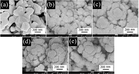
Figure 2. SEM images of BiFe1−xNixO3 nanoparticles: (a) x = 0, (b) x = 0.05, (c) x = 0.1, (d) x = 0.2, and (e) x = 0.3.
Download figure:
Standard image High-resolution imageMoreover, the morphology and structure of the BiFeO3 and Ni-doped BiFeO3 nanoparticles were investigated by TEM. Bright field TEM images, high-resolution (HRTEM) TEM images and corresponding selected areas of electron diffraction (SAED) patterns are shown in figure 3. The TEM bright field images show that the particles sizes obtained were about 30–200 nm. This is in agreement with the XRD and SEM results. To better investigate the crystal structure, HRTEM was performed, which shows the lattice fringes of the (1 0 4), (2 0 2), (1 0 4), (0 1 2) and (1 0 4) planes with interplanar spacing of approximately 0.281, 0.227, 0.281, 0.395, and 0.281 nm of the BiFe1−xNixO3 with x = 0, 0.05, 0.1, 0.2, and 0.3 samples, respectively, which correspond to BiFeO3. This indicates that the nanoparticles are surrounded by BiFeO3 nanocrystals. Moreover, the SAED patterns of the nanoparticles show spotty and ring patterns. The spotty rings show the characteristics of nanocrystalline BiFeO3 (JCPDS No.86–1518).
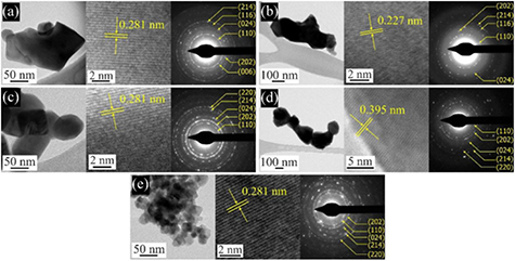
Figure 3. Bright field TEM images (left), high-resolution TEM (HRTEM) images (middle) and corresponding selected areas electron diffraction (SAED) patterns (right) of BiFe1−xNixO3 nanoparticles: (a) x = 0, (b) x = 0.05, (c) x = 0.1, (d) x = 0.2, and (e) x = 0.3.
Download figure:
Standard image High-resolution imageThe normalized XANES spectra of all samples at the Ni and Fe K-edges are shown in figure 4. The Ni K-edge XANES spectra of BiFe1−xNixO3 nanoparticles can be seen with x = 0.05, 0.1, 0.2, and 0.3 as compared with those of the standard materials with different Ni oxidation states. The absorption edge at the Ni K-edge of all the samples match those of Ni+2 of NiO standard samples and the oxidation state of the Ni ion conforms with that of the starting materials (Ni+2), as shown in figure 4(a). Clearly, the oxidation state of Ni is not 3+, but could be 2+. Figure 4(b) shows the XANES spectra at the Fe K-edge of all the samples, which match that of Fe2O3, indicating that the oxidation state of Fe is 3+. Furthermore, the XANES analysis provides strong evidence that Ni+2 (~0.69 Å) of large ionic radius is substituting the Fe3+ (~0.645 Å) site.

Figure 4. XANES spectra of BiFe1−xNixO3 (x = 0, 0.05, 0.1, 0.2, and 0.3) nanoparticles: (a) Ni K-edge and (b) Fe K-edge.
Download figure:
Standard image High-resolution imageThe N2 adsorption-desorption isotherms and pore size distributions obtained by the BJH plot of BiFe1−xNixO3 nanoparticles with x = 0, 0.05, 0.1, 0.2, and 0.3 are shown in figure 5. Generally, the pores of the materials are classified into three groups according to pore size distributions namely, micropores (pore size <2 nm), mesopores (2–50 nm), and macropores (>50 nm). The presence of micropores, mesopores and macropores in particles is shown by the BJH curve (inset of figure 5).
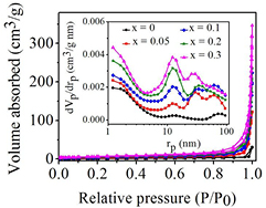
Figure 5. N2 adsorption-desorption isotherms and (inset) pore-size distribution of the BiFe1−xNixO3 nanoparticles.
Download figure:
Standard image High-resolution imageThis may be related to capacitance and capacity retention, which will be discussed in section 3.3. Table 2 shows the specific surface area (SBET), the mean pore diameter (DMP), the total pore volume (VTP), and the particle size (DBET) of BiFe1−xNixO3 (x = 0, 0.05, 0.1, 0.2, and 0.3) nanoparticles. In general, the decrease in the size of BiFeO3 nanoparticles is related to an increase in surface area [9]. In this research, the decreases in the crystallite size led to a sharp increase in the surface area from 3.64 m2 g−1 of the BiFeO3 sample to 21.6 m2 g−1 in the BiFe0.7Ni0.3O3 sample. The particle size decreases from 197.8 nm of un-doped samples to 32.9 nm in 30 % Ni-doped samples were calculated by using the gas absorption technique.
Table 2. Specific surface area (SBET), mean pore diameter (DMP), total pore volume (DTP), particle size (DBET) of BiFe1−xNixO3 (x = 0, 0.05, 0.1, 0.2, and 0.3) nanoparticles.
| Samples | SBET (m2 g−1) | DMP (nm) | VTP (cm3 g−1) | Dmeso (nm) | Vmeso (cm3 g−1) | DBET (nm) |
|---|---|---|---|---|---|---|
| BiFeO3 | 3.64 | 25.55 | 0.0254 | 3.28 | 0.0253 | 197.81 |
| Bi0.95Ni0.05O3 | 9.47 | 49.63 | 0.1175 | 2.42 | 0.1174 | 75.99 |
| Bi0.9Ni0.1O3 | 14.01 | 49.91 | 0.1748 | 24.48 | 0.1748 | 51.33 |
| Bi0.8Ni0.2O3 | 17.65 | 39.07 | 0.1724 | 24.48 | 0.1723 | 40.72 |
| Bi0.7Ni0.3O3 | 21.85 | 39.52 | 0.2159 | 24.48 | 0.2156 | 32.89 |
A comparison of the average crystallite size calculated by XRD and the average particle size estimated by BET showed that the average particle size calculated by BET is larger than the crystallite size calculated by XRD in all samples except for the BiFe0.95Ni0.05O3 sample as shown in figure 6. The difference in the results occurs from aggregates and/or agglomerates of crystals, which indicates that the particles include several crystallites [21]. The presence of the Ni ion in the Fe3+ site acts as an inhibitor and results in a decrease of crystallite size. The inhibition is mainly because of the surface energy of BiFeO3 with the addition of dopant [6, 25]. In this research, we confirm that all the samples with higher concentrations of Ni dopant showed a decrease in particle size which shows a tendency to increase their specific surface area, and total pore volume as calculated and cited in table 2. The increase in the average pore diameter occurs from the agglomeration of the particles that causes sintering of the pores into small ones with decreasing homogeneity of the dimensions and number of pores [21, 26].
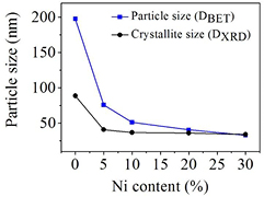
Figure 6. Variations of crystallite size calculated by XRD and particle size calculated from BET of BiFe1−xNixO3 nanoparticles as a function of Ni content (%).
Download figure:
Standard image High-resolution image3.2. Magnetic properties
The magnetic hysteresis (M-H) loops of the BiFe1−xNixO3 (x = 0, 0.05, 0.1, 0.2, and 0.3) nanoparticles at 50, 150, 300, and 350 K of temperature are shown in figures 7(a)–(e). Figure 7(f) shows the saturation magnetization (Ms) increases linearly with increasing Ni doping concentrations at all temperatures. Interestingly, the magnetization of BiFeO3 decreases with decreasing temperature. Conversely, the magnetizations of BiFe1−x NixO3 (x = 0.05, 0.1, 0.2, and 0.3) samples increases with decreasing temperature from 350 to 50 K. The BiFe0.7 Ni0.3O3 sample at a low temperature (50 K) shows the highest magnetization of 22.12 emu g−1. The secondary phase of Bi2Fe4O9 in the x = 0 to x = 0.1 samples does not influence the increases of the Ms because it exhibits an antiferromagnetic nature with a very low Ms, as reported previously [27–29]. By comparison, the magnetization of the BiFe1−x NixO3 (x = 0.05, 0.1, 0.2 and 0.3) samples in this study at room temperature were 0.51, 6.43, 12.20, and 19.12 emu g−1 and at 50 K of temperature were 2.87, 7.45, 14.12, and 22.12 emu g−1, respectively. These results were found to be higher than those reported in the literature, which were 5 % and 25% Ni-doped BiFeO3 at 50 K of temperature (1.29 and 8.04 emu g−1) [7], 10 % Ni-doped BiFeO3 at room temperature (~3.04 emu g−1) [8], and 5% Ni-doped BiFeO3 at room temperature (~1.4 emu g−1) [30].

Figure 7. Magnetization hysteresis loops at different temperature of BiFe1−xNixO3 nanoparticles: (a) x = 0, (b) x = 0.05, (c) x = 0.1, (d) x = 0.2, and (e) x = 0.3. (f) Variations in saturation magnetization as a function of Ni content (%).
Download figure:
Standard image High-resolution imageThe observed increases in the magnetization may arise for two reasons: (1) the magnetization is mainly dependent on the Ni content which provides strong evidence of the effects of the sizes of the BiFeO3 nanoparticles. It is known that particles on the nanoscale exhibit significantly different properties from bulk BFeO3 [31]. Improved magnetization may be due to suppression of the spin cycloid structure of the particle size when it is less than 62 nm which causes the intrinsic spiral spin structure to be incompletely suppressed and the decreases in crystallite size with increases of Ni content results in an increase in surface-volume ratio and the contribution of uncompensated spin at the surface to the total magnetic moment of the particle increases. (2) The high Ms of NiFe2O4 nanoparticles are between 32.1 and 49.1 emu g−1 measured at 300 to 80 K of temperature, respectively [32]. So, the increases of the secondary phase of the NiFe2O4 nanoparticles in the BiFe1−xNixO3 (x = 0.05 to 0.3) samples may cause an increase in saturation magnetization with a decrease in grain size [32–34].
All the samples show the hysteresis loops are field dependent on magnetization measurements indicating weak ferromagnetism with the coercivity (Hc) between 5.51 to 524.34 Oe. The Hc value shows increases with decreases of temperature in all samples. At low temperature (50 K), the BiFeO3 sample shows the highest Hc value of 524.35 Oe. The Hc of all samples increases with low measurements of temperature which may occur for two reasons: (1) an increase in Hc is the alignment of the magnetic moment in the direction of the external magnetic field and (2) thermal fluctuations of nanoparticles decrease with decreases in the temperature [35]. At higher temperatures (350 K), BiFe0.8 Ni0.2O3 shows the lowest Hc value of 5.51 Oe. The variations of Hc decreases when the crystallite size is in the multi-domain region. The particle size dependence on coercivity can be expressed by the [36]
where a and b are constants, and D is the particle size. Thus, the coercivity may decrease with an increase in particle size above a critical size. The Hc of BiFeO3 and BiFe0.95 Ni0.05O3 samples decrease due to a decrease in the crystallite size of BiFeO3 and an increase in temperature. This conforms to the crystallite-size and the temperature-dependent behavior of BiFeO3 [9]. The phase composition of NiFe2O4 may influence Hc in the BiFe1−x NixO3 (x = 0.05 to x = 0.3) samples. The Hc values of NiFe2O4 nanoparticles are between 50 Oe at 300 K and 263 Oe at 80 K [32]. The NiFe2O4 has a critical size of 13–15 nm corresponding to the formation of single domain particles [32]. In this research the crystallite sizes of the NiFe2O4 nanoparticles were 42.7, 20.9, 32.1, and 26.1 nm of BiFe1−x NixO3 (x = 0.05, 0.1, 0.2, and 0.3, respectively) samples. The variations in the Hc values of BiFe1−x NixO3 (from x = 0.1 to x = 0.3) samples at 150–350 K are related to the variations in the crystallite sizes of the NiFe2O4 nanoparticles, especially the decreases of Hc in the BiFe0.8Ni0.2O3 samples. The remanent magnetization (Mr) increases with increases of the Ni content due to decreases in the crystallite size of BiFeO3 at all temperatures, except in x = 0.2 sample at 300 and 350 K, which may be due to the increases of the crystallite size of the NiFe2O4 nanoparticles. Clearly, this is evidence that the size effects of BiFeO3 and NiFe2O4 are strongly influenced by the Hc and Mr values of the BiFe1−x NixO3 nanoparticles at various temperatures.
The zero field cooling (ZFC) and field cooling (FC) magnetization curves of the BiFe1−x NixO3 (x = 0, 0.05, 0.1, 0.2 and 0.3) samples are shown in figure 8, which measured 50 K–350 K in the applied field 500 Oe. The FC curves of the Ni-doped BiFeO3 samples show increases of magnetization with decreases of temperature from 300 to 50 K. This may be attributed to the development of the incommensurate sinusoidal spin structure [37]. The decrease in the magnetization of the ZFC curves (from broad maximum magnetization ~250, 152, 156, 163, and 196 to 50 K) for x = 0, 0.05, 0.1, 0.2, and 0.3 samples, respectively, is evidence indicating the antiferromagnetic exchange interaction of the spins [8]. The deviation between ZFC and FC increases with decreases in temperature. A clear difference between the curves for Ni doped BiFeO3 (x = 0, 0.05, 0.1, 0.2 and 0.3) with increases in the blocking temperatures (TB) of 287, 245, 279, 323, and 310 K was observed, as shown in figure 8. This indicates that there might be magnetic blocking and spin glass behavior [8].
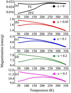
Figure 8. ZFC/FC curves for BiFe1−xNixO3 nanoparticles from 50 to 350 K of temperature.
Download figure:
Standard image High-resolution image3.3. Electrochemical measurements
The cyclic voltammetry (CV), galvanostatic charge- discharge (GVD), and electrochemical impedance spectroscopy (EIS) analyses were used to evaluate the electrochemical performance of the BiFe1−xNixO3 (x = 0, 0.05, 0.1, 0.2, and 0.3) electrodes. All these electrochemical measurements were conducted in 6 M KOH solution using a three- electrode system. Figures 9(a)–(e) show the CV curves of the BiFe1−xNixO3 nanoparticles. The CV measurements were performed between −1.2 V and 0.3 V at different potential scan rates of 5–100 mV s−1 in 6 M KOH solution. The samples exhibited a pseudocapacitive behavior. Redox peaks were observed for all the samples, indicating the redox transitions of the nanoparticles between different valence states. The current response of all electrodes was enhanced when the scan rates were increased. The height of the peak current varied and a progressive shift in the peaks to higher potentials was observed with increasing scan rates from 5 to 100 mV s−1. The calculated specific capacitances versus scan rates are plotted in figure 9(f). The specific capacitances of all the samples decrease with increasing scan rates. This is attributed to the presence of inner active sites, which completely inhibit the redox transitions at higher scan rates of CV, probably owing to the diffusion effect of protons within the electrodes [38]. All the electrodes exhibited the highest specific capacitance at a scan rate of 5 mV s−1. The maximum specific capacitance of 397.3 F g−1 at a scan rate of 5 mV s−1 was obtained for the pure BiFeO3 sample. The specific capacitance of the nanoparticles depends linearly on Ni doping concentrations with continuously decreases.

Figure 9. CV curves of the BiFe1−xNixO3 nanoparticles: (a) x = 0, (b) x = 0.05, (c) x = 0.1, (d) x = 0.2, and (e) x = 0.3. (f) Specific capacitance versus scan rate.
Download figure:
Standard image High-resolution imageThe galvanostatic charge-discharge behavior of the electrodes at current densities from 1 to 20 A g−1 are shows in figures 10(a)–(e). The nonlinear curves confirm the pseudacapacitive behavior of the material. The discharge curve of the electrodes consists of two parts: a steep voltage (IR) drop due to internal resistance and a capacitive component (curved portion) related to the voltage change due to changes in energy within the capacitor [39]. This (IR) drop is a common phenomenon occurring in transition metal oxides [40, 41]. The galvanostatic charge-discharge curves measured in all samples show that current density increases with decreases of the discharge time. The maximum specific capacitance of 513.5 F g−1 at 1 A g−1 current density was obtained from the undoped sample. The specific capacitance at all current densities also continuously decreased from x = 0.05 to x = 0.3 as shown in figure 10(f). This decrease in the capacitance is due to the fact that the surface of the electrode is inaccessible at high charge-discharge rates [16], increasing in ionic resistivity and decreasing in charge diffusion deeper into the inner active sites [40, 42]. Therefore, the specific capacitance of the electrodes at a low current density should be suitable for practical applications. At a current density of 1 A g−1, all the electrodes exhibited the highest specific capacitance.

Figure 10. Galvanostatic charge–discharge curves of the BiFe1−xNixO3 nanoparticles: (a) x = 0, (b) x = 0.05, (c) x = 0.1, (d) x = 0.2, and (e) x = 0.3. (f) Specific capacitance versus current density.
Download figure:
Standard image High-resolution imageIn general, increase in the specific surface area in electrochemical capacitors is a likely reason for the increase in the specific capacitance, especially in carbon materials. On the contrary, the specific capacitance of these BiFe1−xNixO3 nanoparticles decreases from 397.3–183.7 F g−1 in the undoped sample to 194.3–65.4 F g−1 in the BiFe0.7Ni0.3O3 sample (at 5–100 mV s−1 for CV measurement) and 513.6–223.0 F g−1 in the undoped sample to 192.9–30.0 F g−1 in the BiFe0.7Ni0.3O3 samples (at 1–20 A g−1 for GCD measurement) with increases in the specific surface area. However, specific capacitance does not only depend on surface area, but also on other factors, such as the pore size distribution and pore volume [4, 43, 44]. All the samples have distributions of different sizes of pores, namely, micropores, mesopores and macropores, as shown in figure 5, indicating that they have a porous structure, which is specific to supercapacitor materials [43, 44]. The decreases in the specific capacitance of the BiFe1−xNixO3 samples with increases in Ni doping can possibly be attributed to the following: (i) all samples enriched with mesopores show a mean pore diameter of BiFeO3 smaller than the Ni-doped samples; (ii) with regard to mesopore distribution, the BiFeO3 samples showed small mesopore sizes (~3.3 nm) which were smaller than the 10, 20 and 30% Ni doping samples (~24.5 nm), this provides more active sites for chemical reactions [45] and (iii) with regard to macropore distribution, the BiFeO3 sample showed the largest pore in the diameter range of macropores, which provide relatively greater accessibility to the electrolyte for surface adsorption and intercalation, and rapid electrolyte transport and diffusion into the inner region of the electrodes [27, 46–48].
The cycling performance of the BiFe1−xNixO3 (x = 0.05, 0.1, 0.2 and 0.3) electrodes at 10 A g−1 current density are shown in figure 11. The life cycle (stability) of the electrodes is important for practical applications. The capacity retentions of the Ni-doped BiFeO3 samples with x = 0, 0.1, 0.20, and 0.30 were 58, 42, 38 and 35%, respectively, after 500 cycles. Capacity retention can be improved by Ni content. BiFe0.95Ni0.05O3 showed higher capacity retention than the BiFeO3 electrodes. The capacity retention of the BiFe0.95Ni0.05O3 electrode (82%) in this work was higher than that of the BiFe0.95Cu0.05O3 electrode (77.13%) [4]. It increased to 102 % after 80 cycles, and then slightly decreased to 82% after 500 cycles. The capacity retention of over 100% in this electrode was due to the additional cycles needed to fully activate the sample [49, 50]. Improved capacity retention of the BiFe0.95Ni0.05O3 sample may be due to the small mesopore size of about 2.4 nm. This provides more active sites for chemical reactions [45]. This may lead to improvements in the capacity retention in the BiFe0.95Ni0.05O3 electrode. The decreases in the capacity retention with increases of Ni content with x = 0.1 to x = 0.3 may be due to the macropore size distribution, which tends to decrease. This can lead to the suppression of electrolyte diffusion into the inner region of the electrode and active sites for chemical reactions [15, 45]. Moreover, increases in the NiFe2O4 phase composition may influence the specific capacitance due to the fact that the specific capacitance of NiFe2O4 nanoparticles (42.8 F g−1) [51] is lower than that of BiFeO3 nanoparticles (397.3 F g−1) at the same scan rate of 5 mV s−1 in 6 M KOH solution [4]. This indicates that the increases in the phase composition of NiFe2O4 (5.4 to 66.4 %) may lead to decreases in the specific capacitances of the BiFe1−xNixO3 (x = 0.05 to 0.3) samples.

Figure 11. Capacity retention (%) of the BiFe1−xNixO3 electrodes after 500 cycles at 10 A g−1 current density.
Download figure:
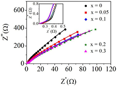
Standard image High-resolution imageEIS analysis is one of the principal methods to examine the fundamental behavior of electrode materials in supercapacitors. The Nyquist plot is a plot relating to the real part (Z') versus an imaginary part (Z'') fitted based on the equivalent circuit having the components of solution resistance (Rs), charge-transfer resistance (Rct), constant phase element (CPE) and Warburg impedance (W). The intercept in the Z' axis at a high frequency refers to Rs which stand for ohmic resistance of the electrolyte, internal resistance of the electrode material and contact resistance at the electrode/current collector interface [40]. Figure 12 shows Nyquist plots of the BiFe1−xNixO3 (x = 0, 0.05, 0.1, 0.2, and 0.3) electrodes. The small values of Rs of the BiFe1−xNixO3 (x = 0, 0.05, 0.1, 0.2, and 0.3) electrodes are 0.24, 0.25, 0.26, 0.25, and 0.24 Ω, respectively, which suggests that all electrodes provide good electrical conductivity of the electrolyte. The semi-circle at high frequency corresponds to Rct. The small values of Rct of the BiFe1−xNixO3 (x = 0, 0.05, 0.1, 0.2, and 0.3) electrodes are 0.13, 0.07, 0.08, 0.10, and 0.09 Ω, respectively, which indicates that all the electrodes providing the charge transfer performance at the electrode/electrolyte interface are facile [40]. Generally, the high capacitance can be attributed to the high surface area and enhanced electrical conductivity of the electrodes [52]. But in this work, variations in the specific capacitances and capacity retention of the Ni-doped BiFeO3 electrodes are not attributed to slight increases of surface area and slight differences in the Rct and the Rs values. The curves move away from the vertical line corresponding to increases in Ni doping concentrations with x = 0, 0.05, 0.1, 0.2, and 0.3. Interestingly, the straight lines close to 90° are parallel to the imaginary axis at low frequencies indicate a pure capacitive behavior and low diffusion resistance of ions in the structure of the electrode. The more vertical the curve the more closely the supercapacitor performs as an ideal capacitor [52–54]. This corresponds to the high specific capacitances in the BiFeO3 electrodes which provide a more perfect capacitance than the Ni-doped BiFeO3 samples and are related to the decreasing capacity retention in the BiFe1−xNixO3 with x = 0.1 to x = 0.3 samples.
Figure 12. Nyquist plots of the BiFe1−xNixO3 (x = 0, 0.05, 0.1, 0.2, and 0.3) electrodes.
Download figure:
Standard image High-resolution image
4. Conclusions
BiFe1−xNixO3 (x = 0, 0.05, 0.1, 0.2, and 0.3) nanoparticles were successfully synthesized by a simple solution method. The structures and morphologies of all the samples were characterized by XRD analysis, SEM, TEM, XAS, the BET method, and the BJH method. The oxidation state of Ni ions was also confirmed from the XAS results. The effects of Ni doping on the magnetic and electrochemical properties of the BiFe1−xNixO3 nanoparticles were discussed. Ni-doped BiFeO3 nanoparticles exhibit weak ferromagnetic behavior. Ni-doped BiFeO3 nanoparticles also exhibit enhancements of the Ms and Mr values. The BiFe0.7 Ni0.3O3 nanoparticles in this study show the magnetization at room temperature (19.12 emu g−1) and at 50 K of temperature (22.12 emu g−1) which is higher than that reported in the literature: 5 and 25% Ni-doped BiFeO3 at 50 K (1.29 and 8.04 emu g−1) [7], 10 % Ni-doped BiFeO3 at room temperature (~3.04 emu g−1) [8], and 5% Ni doped BiFeO3 at room temperature (~1.4 emu g−1). The Ms, Hc and Mr values are dependent on the crystallite size of BiFeO3 and NiFe2O4. The ZFC and FC magnetization curves of the Ni doped BiFeO3 nanoparticles were observed with increases in blocking temperatures (TB). The nanoparticles were fabricated as electrodes in order to study their electrochemical properties. The effects of Ni-doped BiFeO3 on the electrochemical properties of the nanoparticles were discussed. The specific capacitance depends linearly on Ni doping concentrations when continuously decreased from x = 0 to x = 0.3. But the BiFe0.95Ni0.05O3 electrodes with a small mesopore size exhibit an enhanced capacity retention as high as 82 % after 500 cycles, which can be considered as a good candidate for use in supercapacitors.
Acknowledgments
The authors would like to thank the Synchrotron Light Research Institute (BL5.2), Nakhon Ratchasima, Thailand, for the use of XANES and XPS facilities, and the Department of Physics, Faculty of Science, Khon Kaen University, Khon Kaen, Thailand, for VSM facilities. This work was supported by Suranaree University of Technology (SUT) and by Office of the Higher Education Commission under NRU Project of Thailand.