
Abstract
This paper reports on the fabrication of non-chapped, vertically well aligned titanium dioxide nanotubes (TONTs) by using electrochemical etching method and further heat treatment. Very highly ordered metallic titanium nanotubes (TNTs) were formed by directly anodizing titanium foil at room temperature in an electrolyte composed of ammonium fluoride (NH4F), ethylene glycol (EG), and water. The morphology of as-formed TNTs is greatly dependent on the applied voltage, NH4F content and etching time. Particularly, we have found two interesting points related to the formation of TNTs: (i) the smooth surface without chaps of the largely etched area was dependent on the crystalline orientation of the titanium foil; and (ii) by increasing the anodizing potential from 15 V to 20 V, the internal diameter of TNT was increased from about 50 nm to 60 nm and the tube density decreased from 403 tubes μm−2 down to 339 tubes μm−2, respectively. For the anodizing duration from 1 h to 5 h, the internal diameter of each TNT was increased from ∼30 nm to 60 nm and the tube density decreased from 496 tubes μm−2 down to 403 tubes μm−2. After annealing at 400 °C in open air for 1 h, the TNTs were transformed into TONTs in anatase structure; further annealing at 600 °C showed the structural transformation from anatase to rutile as determined by Raman scattering spectroscopy.
Export citation and abstract BibTeX RIS

Original content from this work may be used under the terms of the Creative Commons Attribution 3.0 licence. Any further distribution of this work must maintain attribution to the author(s) and the title of the work, journal citation and DOI.
1. Introduction
Titania, TiO2, has been extensively studied with a view to various applications in environmental depollution technology, generation of hydrogen gas, photovoltaics, gas sensors, immobilization of biomolecules in biosensors [1–10] due to its high photo-activity [1–5], biocompatibility [4, 5], low toxicity and low cost, good chemical and thermal stability [1–5]. The physicochemical properties of nanomaterials in general and TiO2 in particular are dependent on their structural properties including size, shape and crystallinity. Recently, nanotubular TiO2 has been seen as considerably attractive due to its exceptional properties and excellent applications to photocatalyst and solar cell [11–13]. TiO2 nanotutes have been synthesized by various methods such as electrochemical anodization, sol–gel, microwave irradiation, and other methods involving the chemical/hydrothermal treatment of titania particles. Among the methods, electrochemical anodization/etching could produce the highly ordered nanotubular arrays. This highly oriented tubular structure is more favoured compared to the randomly nanoparticular suspensions synthesized by other methods in view of application, for example, in photocatalytic systems or dye-sensitized solar cells [13, 14]. The disordered nanostructures and vast grain boundaries result in small surface area and the fast recombination of photo-generated electrons and holes. In contrast, the large surface area provided from the nanotubular walls (inside and outside surfaces) in addition to the porosity structure will facilitate light harvesting, create a unidirectional electrical channel, and allow for much larger reaction interface with high energy conversion abilities. Zwilling fabricated the first generation of titania nanotube array by anodization in acidic HF-based electrolytes, and TiO2 nanotube arrays could be grown up to a length of 500 nm [11]. The results from Schmuki indicated that the TiO2 nanotube array length could be increased up to 7 μm when the pH of the anodization electrolyte was kept in neutral by using NaF or NH4F instead of HF [14]. After that, Grimes reported a new generation of vertically oriented TiO2 nanotubes with length up to 134 μm by using various non-aqueous electrolytes [15]. From the literature one could see a problem that even though titanium nanotubes (TNTs) were well formed by electrochemical anodization, in a sufficient area of sub-square micrometers there appeared many chaps on the surface of TNTs foils [13, 16–18]. To the best of our knowledge, little attention has been paid to the influence of the crystalline orientation on morphological properties of titanium nanotubes, especially for forming non-chapped, well-organized TNTs array directly on titanium substrates.
In this paper, we report the synthesis of non-chapped, vertically well aligned titania nanotubes arrays with different diameters of tube, and the characterization of their morphology and structure. The morphology of nanotubes could be controlled by changing the technical parameters such as the etching potential, the NH4F content in the electrolyte, etching time, and the crystalline orientation of titanium substrate. The experimental results showed that with increasing the anodizing potential from 15 V to 20 V, the internal diameter of TNT was increased from ∼50 nm to 60 nm and their density decreased from 403 tubes μm−2 down to 339 tubes μm−2. The TNTs were well formed with the NH4F concentration in the electrolyte of 0.3 wt% or larger. To obtain nice TNTs arrays the etching time must be longer than 3 h. For anodizing duration from 1 h to 5 h, the internal diameter of each TNT was increased from ∼30 nm to 60 nm and the tube density decreased from 496 tubes μm−2 down to 403 tubes μm−2. The crystalline orientation of titanium substrate has been determined to be the most important factor to make TNTs in a large area without chaps. The as-prepared TNT films were calcined at 400 °C or 500 °C to form the crystalline anatase phase, and then at 600 °C to transform anatase phase into rutile one.
2. Experimental
Titanium foils of 0.1 mm thickness and high purity of 99.7% were used in experiments to prepare TiO2 nanotube arrays by electrochemical etching method. Before etching, the titanium sheets (10 mm × 10 mm) were degreased by ultrasonic treatments with acetone, ethanol, and distilled water for 10 min, respectively. After drying in air, this titanium sheet was contacted and then pressed against the 0.6 mm diameter O-ring into an electrochemical cell made from teflon. The electrochemical set-up included the second electrode with platinum net as the cathode. These two electrodes were separated by a distance of 2 mm. Anodizing was performed in the mixed solution containing ethylene glycol, NH4F and distilled water [1]. Three series of experiments were performed to check the technological parameters which influence the final TNTs quality. (i) To determine the suitable applied voltage, the anodizations were performed at different electrical potentials of 5–20 V while other technological parameters remained unchanged: the mixed solution was made from ethylene glycol, 0.3 wt% NH4F and 2 vol% distilled water; the etching time was for 5 h. (ii) After determining the suitable applied voltage to be 15 V, the anodizations with different NH4F concentrations ranging from 0.1% to 1.0% (mass fraction) were carried out for 5 h. (iii) Lastly, to check the influence of the etching duration, the anodizations for 1–5 h were carried out in the mixed solution of ethylene glycol, 0.3 wt% NH4F and 2 vol% distilled water with the 15 V potential. After anodization, TNTs were immediately taken out of the electrolyte and washed with distilled water followed by acetone, ethanol to remove the occluded ions from the anodized solutions and dried in vacuum. The as-prepared TNT films were subsequently annealed in open air at 400–600 °C for 1 h to convert the TNTs to the crystalline anatase or rutile phase, namely TONTs. The morphologies and structures of the nanotubes were analyzed using scanning electron microscopy (SEM, Hitachi S-4800) and Raman scattering spectroscopy (Labram HR800, Horiba).
3. Results and discussion
The various technological parameters (such as the etching time, applied voltage, the NH4F content in the electrolyte, and the crystalline orientation of titanium foils substrate) have been systematically investigated to change the morphological properties of the obtained TNTs, including the internal tube's diameter and length, wall thickness and roughness, as well as the degree/density of ordering of the aligned nanotubes. Figure 1 shows the SEM images of the TNTs' surface structures obtained with different anodizing voltages (5–20 V) for 5 h in the mixed solution of ethylene glycol, 0.3 wt% NH4F and 2 vol% distilled water. At low voltage of 5 V, it can be seen that inhomogeneous nanotubes could be observed but the titanium foil surface looks rough and covered by precipitates [19]. When the applied voltages were increased to 15 V or higher (20 V), the uniformity of TNTs are clearly demonstrated on the entire surface. Depending on the voltage applied for electrochemical etching, the average internal diameter of TNTs was increased with increasing voltage, from ∼15 nm at 5 V, 50 nm at 15 V to 60 nm at 20 V; and the density of TNTs was decreased from 403 tubes μm−2 for the 15 V potential to 339 tubes μm−2 for the 20 V one. This first experimental series shows that the TNTs' diameter and their density are strongly dependent on the voltage applied for electrochemical etching. Analyzing the SEM images obtained from many experiments we have determined that 15 V is sufficient for forming nice TNTs with internal diameters of several ten nanometers.

Figure 1. SEM images of the TNTs arrays fabricated by anodization in the ethylene glycol and water mixed solution for 5 h as a function of applied voltages (indicated in the figures).
Download figure:
Standard image High-resolution imageThe mechanism for TNT formation could be explained in terms of a competition between several electrochemical and chemical reactions, including the primary oxidation reaction that occurs at the metal/oxide interface of the anode, most likely are as follows:

In the electrolyte, protons and hydroxyls, consumed at the cathode and anode, respectively, are replaced by the auto-ionization of water:

Finally, at the cathode, electrons from the anode generated in reaction (1) are consumed typically by evolving hydrogen from the protons produced in reactions (1) and (2):

Together these reactions give the net cell reaction:

In addition to the oxidation reaction, dissolution reactions also occur and play a very important role in nanotube formation and morphology. The presence of fluorides in the electrolyte causes the chemical dissolution of the titanium oxide to form the water-soluble [TiF6]−2 complex. On the other hand, the complex also occurs with the Ti4+ ions that are ejected at the interface of oxide-electrolyte by the following overall reactions [20–26].


Based on the reactions shown above, one can see that the formation and morphology of TNTs depend on the fluoride concentration. Therefore, we carried out the second experimental series with the anodizations in different NH4F concentrations ranging from 0.1% to 1.0% (mass fraction) at 15 V for 5 h. The results showed that the only pits were observed on rough surface of array with low fluoride concentration of 0.1 wt%, indicating the fluoride content was only enough for dissolving the small areas of the initial titanium oxide layer to form the pores. When the percentage of NH4F in the electrolyte increased from 0.3 wt% to 1 wt%, which was high enough to actively promote the rate of [TiF6]−2 formation and dissolution equal to the rate of TiO2 layer formation, the uniform nanotutes were obtained. In addition, the thickness of the TNTs' wall was slightly decreased with increasing the NH4F concentration in the electrolyte.
After having determined the suitable applied voltage to be 15 V and the NH4F concentration of 0.3 wt% or larger, the third experiment on the etching time for 1–5 h was performed. Figure 2 illustrates the evolution with time of the morphology of TNT arrays formed at the 15 V potential in the mixed solution of ethylene glycol and distilled water containing 0.3 wt% NH4F. At shorter etching time (<2 h), the surface arrays could be observed both of the tubes and small pits, which were assumed due to the localized dissolution of oxide (figures 2(a), (b)). And then these pits could act as the pore forming centers to develop the tubes. To obtain nice TNTs arrays the etching time must be longer than 3 h. Note that the internal diameters of TNTs and the tube density changed much with the etching time, namely for the etching duration from 1 h to 5 h, the internal diameter of each TNT was increased from ∼30 nm to 50 nm and the tube density decreased from 496 tubes μm−2 down to 403 tubes μm−2, respectively.
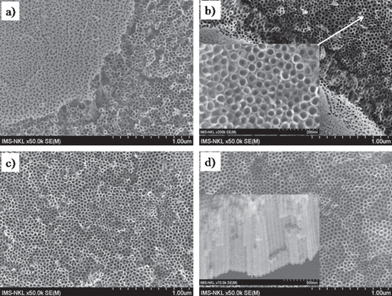
Figure 2. Top-view SEM images of the surface TNT arrays obtained by anodization at 15 V in the mixed solution of ethylene glycol and water (2 vol%) containing 0.3 wt% NH4F at different anodizing/etching time: (a) 1 h; (b) 2 h; (c) 3 h and (d) 5 h. The insets show the corresponding surface and cross-sectional images.
Download figure:
Standard image High-resolution imageBecause the internal diameter of TNTs and the tube density change much with the etching time, this means that each TNT did not grow exactly in the vertical direction deeper into the titanum foil from its surface. This also means that along with the etching a certain method must be applied to release the void area needed to form all the TNTs from the top (at the surface of titanium foil) to the bottom (in contact with the remaining titanium substrate). If the stress/strain exists on the titanium foil's surface or the crystalline facet is not favourable for etching smoothly, i.e. to release gradually the void to compensate the need of the change in the tube diameter and density, chaps would appear as observed in the literature [13, 16–18]. We believe that the Ti atom density is different at different crystalline facet that makes the etching rate different correspondingly. Figure 3 illustrates the surface morphology of the TNT arrays obtained with different crystalline orientation. The cracked surface could be observed with the (001) oriented titanium substrate while the smooth surface was obtained for the (101) oriented one. This is a very nice guide for making highly ordered, vertically well aligned, non-chapped TNTs by electrochemical etching method.
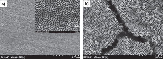
Figure 3. Top-view SEM images of highly ordered TNTs fabricated by electrochemical etching on (101) facet (a) and (001) facet (b) at 15 V for 5 h in the mixed solution of ethylene glycol and water.
Download figure:
Standard image High-resolution imageOur aim is to fabricate TONTs on the titanium substrate. Therefore, after obtaining nice metallic TNTs we need to oxidize them into oxide form. Figure 4 presents the SEM images of the as-anodized and heat-treated TNT arrays at 400 °C for 1 h in the ambient atmosphere. It can be seen that the wall thickness of nanotubes was increased a few nanometers after annealing. The improvability of wall thickness could facilitate some practical applications [27].

Figure 4. SEM images of the sample fabricated by anodization at 15 V for 5 h in ethylene glycol and water (2 vol%) mixed solution: (a) before and (b) after annealing at 400 °C for 1 h in open air. The inset is the SEM image showing the side view of the wall structure.
Download figure:
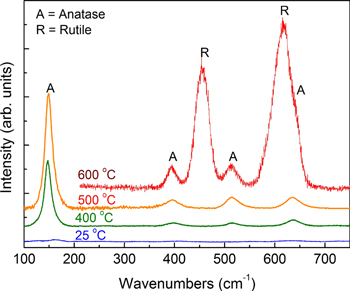
Standard image High-resolution imageFigure 5 shows the Raman spectra of TONTs after calcinations of TNTs at different temperatures ranging from 400 to 600 °C. Raman spectroscopy is a very powerful tool to determine various structural phases including glassy and crystalline, especially to distinguish the different crystalline structures which are based on the same chemical formula, e.g. anatase and rutile have the same TiO2 formula [28]. The results demonstrate the effects of the calcinations temperature on the structural phase of TiO2 nanotubes on the Ti substrate. As-formed TNTs might have some TONTs on the surface but their very thin layer or amorphous structure make them not show any well-defined Raman peaks (the bottom curve of figure 5). When the TNTs sample was calcinated at 400 °C, the Raman spectrum presents peaks with wavenumbers of 147, 397, 514 and 633 cm−1, which are all typically assigned to the anatase phase. No peaks either related to rutile or other TiO2 polymorphs were observed for this sample. When calcining TNTs sample at 600 °C, the anatase phase was partially transformed into rutile showing the typically strong Raman peaks at 453, 610 cm−1.
Figure 5. Raman spectra of anodized TNTs after annealing at different temperatures (indicated in the figure) showing formation of anatase and rutile (labeled A and R, respectively) by oxidation of metallic titanium.
Download figure:
Standard image High-resolution image
4. Conclusion
Non-chapped, highly ordered and vertically well aligned TONTs were fabricated by electrochemical etching in the mixture solution of ethylene glycol and distilled water containing NH4F and further thermal treatment. The morphologies of TNT arrays were greatly dependent on the applied potential, the NH4F content, and the etching time. By increasing the etching potential from 15 V to 20 V, the internal diameter of TNT was increased from 50 nm to 60 nm and the tube density decreased from 403 tubes μm−2 down to 339 tubes μm−2, respectively. The NH4F content of 0.3 wt% or higher in the mixed solution of ethylene glycol and distilled water (2 vol%) was needed to obtain high quality TNTs. For the etching time from 1 h to 5 h, the internal diameter of each TNT was increased from ∼30 nm to 50 nm and the tube density decreased from 496 tubes μm−2 down to 403 tubes μm−2, respectively. Based on the experimental results, a set of technological parameters such as 15 V potential, a mixed solution of ethylene glycol with 0.3 wt% NH4F and 2 vol% distilled water, and 5 h etching time is determined to produce nice TNTs with internal diameter of 50 nm and tube density of 403 tubes μm−2. Particularly, we have found that the smooth surface of the TNTs film without chaps in the largely etched area was dependent on the crystalline orientation of the titanium foil, namely the best with the (101) facet. After annealing at 400 °C in open air for 1 h, the TNTs were transformed into TONTs in anatase structure; further annealing at 600 °C showed the structural transformation from anatase to rutile.
Acknowledgment
This work was supported by Vietnam Academy of Science and Technology (HTCBT13.13 project) and EU-FP7 NMP.2012.2.2-6 Program (PCATDES project). UTDT benefits from the JWT Jones Travelling Fellowship Grant. The authors also thank the National Key Laboratory for Electronic Materials and Devices-IMS for the use of facilities.