
Abstract
This paper reports the results on the syntheses of high-quality (with luminescence quantum yield reaching ∼70%) CdTe and CdTe/CdS core/shell quantum dots (QDs) in water at temperatures below 100 °C. The same CdTe seed QDs (of 2.5 nm in size to emit luminescence at 494 nm) were used as a stock to develop CdTe/CdS core/shell QDs at 90 °C with different CdS shell thicknesses. By progressively increasing the CdS thickness we could make CdTe/CdS core/shell QDs changing from type-I into type-II quantum structure to emit strong luminescence peaking in the spectral range of 550–800 nm. By exciting directly the CdTe core QDs in a type-II CdTe/CdS core/shell structure, we could determine the luminescence decay-time to be as long as 190 ns which is very much longer than that from the type-I ones.
Export citation and abstract BibTeX RIS

Content from this work may be used under the terms of the Creative Commons Attribution 3.0 licence. Any further distribution of this work must maintain attribution to the author(s) and the title of the work, journal citation and DOI.
1. Introduction
Nanomaterials, and particularly semiconductor quantum dots (QDs), have gained much attention from both the fundamental and applied research points of view [1–16]. One could mention the achievements in the syntheses of high-quality CdSe, CdTe, InP, GaN QDs and their core/shell structures in which the shell is usually a material with the larger bandgap energy such as CdS, ZnSe or ZnS. Depending on the band offset, the core/shell structure can be type-I or type-II and their possible applications would change accordingly. Type-I core/shell QDs could strongly emit luminescence because the excited electrons and holes are confined in the same material, while type-II core/shell QDs give more chance for separating the excited electrons and holes because of the band offset. Type-I core/shell QDs, therefore, are very good candidates for applications in biolabeling, fluorescence sensing and in light- emitting diodes [1–9, 11–16], while type-II QDs are promising for photovoltaic and photocatalytic applications with fast separation of the excited electrons and holes. Because the total energies of the electrons and the holes in QDs depend not only on the nature of material but also on the charge confinement in QDs, one can manipulate the band-edge alignment to have the type-I or type-II quantum structure, namely by the bandgap engineering with adjusting the size of the core QDs and/or the thickness of the shell. There are some core/shell QDs with very small band-offset between the core and the shell in the one band, e.g. CdSe/ZnSe with nearly the same hole band, and CdTe/CdS with the near electron band [17]. For the particularly mentioned core/shell QDs one can design the size of the core QDs and change the thickness of the shell to tune the relative band offset between the core and the shell so that the core/shell structure may transit from type-I to type-II.
In the past, there have not been so many publications on the CdTe/CdS core/shell QDs [1,5,8]. This might be due to less confinement of the excited electrons in the CdTe core QDs consequently giving rise to less luminescent quantum yield (LQY) which is not positive for emitting light. Meanwhile, there have been other core/shell systems such as CdSe/ZnS, CdSe/ZnSe/ZnS which could emit luminescence at different wavelengths from visible to deep-red with very high LQY [1–4,13–15,18–20]. Recently, because of the interests in making type-II quantum structure for photovoltaic applications and for light emitting in the near-infrared (NIR) region, these type-II CdTe/CdS core/shell QDs have become more considered [8, 21–26]. CdTe QDs could be synthesized in water with 3-mercaptopropionic acid as surfactant or in oil medium with balancing the coordinating capacity and selected surfactants [21,27–31]. Then CdS and/or CdS/ZnS or CdS/ZnO shelling made CdTe/CdS core/shell or CdTe/CdS/ZnS or CdTe/CdS/ZnO core/shell/shell QDs highly luminescent (LQY of 50–90%). By changing the size of the CdTe core, or the thickness of the CdS shell, the emission colors of the obtained core/shell nanocrystals can be tuned between visible and near-infrared.
In this paper we present the aqueous syntheses of small CdTe and CdTe/CdS core/shell QDs with different thicknesses of the CdS shell, the characterization of their morphology and structure, their absorption and photoluminescence properties. The results showed that with progressively increasing the CdS thickness while the CdTe core size unchanged, the CdTe/CdS core/shell QDs could transit their structure from type-I to type-II to emit strong luminescence peaking in the spectral range of 550–800 nm. By photoexciting directly to the CdTe core QDs using the 532 nm laser light, we measured the luminescence decay time to be as long as 190 ns, which is very much longer than that from the type-I ones.
2. Experimental
2.1. Chemical substances
Chemical agents for the synthesis of CdTe and CdTe/CdS QDs are: cadmium bromide (CdBr2, 99%), 3-mercaptopropionic acid (MPA, 99%), mercaptosuccinic acid (MSA), sodium borohydride (NaBH4, 99%) and TeO2. They were purchased from Merck and Aldrich. All chemicals were used without additional purification.
2.2. Synthesis of CdTe/CdS QDs
CdTe QDs were synthesized in aqueous solution following the procedure described elsewhere [32, 33]. Briefly, a stock NaHTe solution was quickly injected into CdBr2 solution at room temperature in the presence of MPA or MSA as a stabilizing agent to create the CdTe nanocrystals (hereafter called CdTe seed QDs). The molar ratio of Cd:Te:MPA(MSA) was fixed at 1:0.1:1.5 and the pH of this solution was adjusted in the range of 7–8 by adding the 1.0 M NaOH stock solution. Then, the CdTe seed QDs were used directly for shelling at 90 °C or were grown up in an autoclave at 120 °C for different growth times between a few minutes to several hours that would enable us to obtain the high- quality CdTe QDs with different sizes. In the present study, the same source of CdTe seed QDs was used to prepare the so-called CdTe core QDs (without the CdS shell) and CdTe/CdS core/shell QDs (with the CdS shell having different thicknesses). All the CdTe core QDs and CdTe/CdS core/shell QDs underwent the same heat treatment at 90 °C, pH ∼ 12 for 3 h. The CdS shelling was performed by adding the stock solution made of 86 mg of CdBr2 and 37 μl of MPA in 10 ml of distilled water, and the S precursor (from thiourea, which would be dissolved at the shelling temperature to provide the S2− ions) with the corresponding amount of thiourea calculated to form 1, 2, 3, 5 and 7 monolayer (ML) of CdS into the very Cd2+-rich solution containg CdTe seed QDs. The obtained CdTe QDs and CdTe/CdS core/shell QDs could be precipitated by adding drops of ethanol or acetone into QDs-containg colloids, then centrifugated. In the final QDs all the excessive Cd2+ ions and by-pass products from the as-synthesized QDs colloidal solution could be washed. The precipitated QDs were redispersed in distilled water and kept at the normal room condition for use afterwards.
2.3. Characterizations
CdTe core and the CdTe/CdS core/shell QDs were characterized by transmission electron microscopy (TEM, model JEOL 1010) and x-ray diffraction (XRD, Siemens D5000) for morphology and crystalline structure, by optical measurements including absorption and photoluminescence (PL). In the steady-state PL measurements, a 405 nm laser diode was used as the excitation source. For the time-resolved PL (TRPL) measurements, the 532 nm pulsed light from a frequency-doubled Nd:YVO4 laser (700 ps pulse duration, 7 kHz repetition rate) was used as the excitation source to excite directly the CdTe core (to avoid interference excitation to the CdS shell). The PL signals were dispersed by using a 0.6 m grating monochromator (Jobin-Yvon HRD1 or Horiba iHR550) and then detected by using a thermoelectrically cooled Si-CCD camera (Synapse) for the steady-state PL measurement and a fast photomultiplier (Hamamatsu model H733, with the rise time of 700 ps) for the TRPL measurements. Averaging the multi-pulses at each spectral point using a 1.5 GHz digital oscilloscope (LeCroy 9362) strongly improved the signal-to-noise ratio.
3. Results and discussion
A large amount (in gram scale) of the CdTe seed QDs was synthesized to be used as the same source for preparing CdTe/CdS core/shell QDs without (0 ML of CdS, i.e. the CdTe core QDs) and with 1, 2, 3, 5 and 7 ML of the CdS shell. Figure 1 shows the TEM images and the size-distribution of CdTe seed QDs and CdTe/CdS core/5 ML shell QDs. The inset is a high-resolution TEM image showing the atomic facets of an example dot. The crystallinity of synthesized QDs was checked by using XRD method. After heating at 90 °C for 3 h the CdTe seed QDs became CdTe core QDs with the size of 3.5 nm. The sizes of CdTe/CdS core/shell QDs were increased with increasing the number of MLs of the CdS shell. Having 5 ML CdS shell, the CdTe/CdS core/shell QDs are as big as 7 nm.

Figure 1. TEM images and the size-distribution of (a) CdTe QDs and (b) CdTe/CdS core/5 ML shell QDs. The inset is a high-resolution TEM image showing the atomic facets of an example dot.
Download figure:
Standard image High-resolution imageFigure 2 shows the XRD pattern of tiny 2.5 nm seed CdTe nanoparticles, 3.5 nm CdTe core QDs (cubic) and of 7 nm CdTe/CdS QDs with the 5 ML CdS shell. The XRD pattern of the thick CdS shelled QDs shows mainly hexagonal structure from CdS because the CdS shell is much larger in volume comparing to the CdTe core QDs. Note that the QDs sizes determined from XRD pattern and from the absorption spectra are usually smaller than those obtained by using dynamic light scattering measurement. This is reasonable due to the contribution of ligands in the colloidal samples used in the latter one. From the TEM images and XRD patterns one can see the good crystallinity of the synthesized samples.
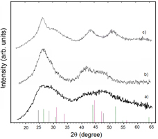
Figure 2. X-ray diffraction pattern of (a) tiny seed CdTe nanoparticles, (b) 3.5 nm CdTe core QDs (cubic) and (c) CdTe/CdS core/shell QDs with the 5 ML CdS shell (hexagonal).
Download figure:
Standard image High-resolution imageWe now show the results from the study of the optical properties of the CdTe/CdS core/shell QDs with different CdS thicknesses. Figure 3 shows the absorption and PL spectra of the CdTe seed QDs, CdTe core QDs (i.e. CdTe seed QDs grown at 90 °C for 3 h), and CdTe-core/1 and 5 ML CdS-shell QDs shelled at 90 °C for 3 h. The absorption spectra from CdTe seed QDs, CdTe core QDs and even from the CdTe-core/1 ML CdS-shell QDs exhibit very nice excitonic transition again showing good crystallinity of the QDs under study. For the CdTe-core/5 ML CdS-shell QDs the less humpy excitonic transition in the absorption spectrum and the great red-shift of the PL spectra compared to those from the CdTe-core/1 ML CdS-shell QDs are resulting from the type-II quantum structure, as evidenced in the following discussion. We used CdTe core QDs to start the CdS shelling with the expectation of getting type-I CdTe/CdS quantum structure with the thin CdS shells. This is because contributions of the confinement energies of the electrons and holes in thin CdS shells that shift the band-edges of CdS to be higher in conduction band and lower in valence band compared to those from CdTe core QDs. Then, along with thickening the CdS shell to reduce the confinement energies of the electrons and holes, the conduction band-edge of CdS would be lower to fulfill the type-II CdTe/CdS structure condition. It is interesting to observe such characteristics with a very clear transition from type-I into type-II as shown in figure 4. The absorption and PL spectra of CdTe-core/CdS-shell QDs with different CdS shell thicknesses from 0 to 7 ML. The red-shift of the spectra from the CdTe-core/1 ML CdS-shell QDs compared to those from the CdTe core QDs demonstrates the shelling but not alloying process. Then, along with the thickening the CdS shell, the corresponding spectra are red-shifted. At certain CdS shell thicker than 3 ML one can notice a clear change to be less humpy in the excitonic absorption to show the type-II CdTe/CdS quantum structure. Another feature that should be mentioned is that, along with thickening the CdS shell, not only does the excitonic absorption of CdTe core QDs become less humpy, but also the Stokes shift is much reduced accordingly. This might be related to less localization of the charge carriers in such structures. In comparison with that of CdSe QDs, the Stokes shift in CdTe QDs is really very large, hundreds of meV, and is questionable. Naturally, with less localization and less confinement of the charge carriers, the recombination rate of such excited carriers is decreased, giving rise to reduction of the LQY. Figure 4(b) shows the corresponding PL peak positions and LQYs of CdTe/CdS core/shell QDs with different CdS thicknesses. The highest LQY is achieved from the type-I CdTe/CdS core/shell QDs with the 2 ML CdS shell which passivated well the CdTe core QDs but is not relaxed yet by the lattice mismatch between CdTe and CdS.
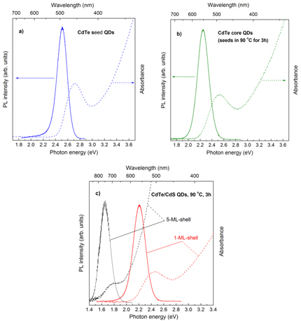
Figure 3. Absorption and PL spectra of the (a) CdTe seed QDs, (b) CdTe core QDs and (c) CdTe-core/1 and 5 ML CdS-shell QDs.
Download figure:
Standard image High-resolution image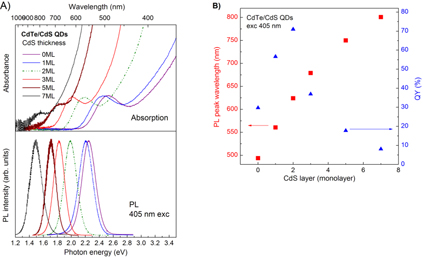
Figure 4. (A) Absorption and PL spectra of CdTe-core/CdS-shell QDs with different shell thicknesses from 1 to 7 ML, and (B) corresponding peak positions and LQYs.
Download figure:
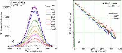
Standard image High-resolution imageTo prove the formation of the type-II quantum structure the PL decay-time was measured. Figure 5 show the typical results of the TRPL spectra and decay times of the CdTe-core/5 ML CdS-shell QDs. The choice of the 532 nm laser light for excitation allows generation of the excited charge carriers just inside the CdTe core QDs. Then, by very fast separation of the excited electrons from the CdTe core to the CdS shell [34], these photogenerated electrons could recombine with the holes in the CdTe core QDs to emit light but in a not very large rate, or correspondingly exhibit as the PL with much longer decay time. The decay times taken at three different PL wavelengths before the peak, at right peak and after the peak emission from type-II CdTe/5-ML-CdS QDs are to be of 175, 190 and 200 ns, respectively. The longer emission wavelength the longer decay time results from the energy transfer from the smaller QDs (higher energy) to larger QDs (lower energy). These decay-times are much longer than the reported ones for similar materials that are usually less, hundreds of ns [28, 34].
Figure 5. (a) Time-resolved PL spectra and (b) decay-times of the CdTe-core/5 ML CdS-shell QDs at three different PL wavelengths (indicated) around the peak emission.
Download figure:
Standard image High-resolution image
4. Conclusion
In conclusion, we have reported the results on the aqueous syntheses of high-quality CdTe QDs and then shelling with 1–7 ML of CdS, and the characterizations of morphology and structure, their absorption and photoluminescence properties. By progressively increasing the CdS shell thickness we could make CdTe/CdS core/shell QDs changing from type-I into type-II quantum structure to emit strong luminescence peaking at 550–800 nm. By using the 532 nm laser light to excite directly to the CdTe core QDs in a type-II CdTe/CdS core/shell structure, we determine the luminescence decay time to be as long as 190 ns. Besides the high separation rate of the photogenerated electrons and holes that is a good characteristic for photovoltaic and photocatalytic applications, the strong NIR luminescence with very long decay time is a practically nice feature for biosensing application.
Acknowledgments
UTDT thanks Acad. Nguyen Van Hieu at VAST for his kind and continuous encouragement and UNESCO-L'OREAL Vietnam National Fellowship the Award `Women in Science'.