
Abstract
High energy x-ray targets are the anodes used in high performance tubes, designed to work for long operating times and at high power. Such tubes are used in computed tomography (CT) scan machines. Usually the tubes used in CT scanners have to continuously work at high temperatures and for longer scan durations in order to get maximum information during a single scan. These anodes are composed of a refractory substrate which supports a refractory metallic coating. The present work is a review of the development of a ceramic metal composite based on aluminium nitride (AlN) and molybdenum for potential application as the substrate. This composite is surface engineered by coating with tungsten, the most popular material for high energy x-ray targets. To spray metallic coatings on the surface of ceramic matrix composites dc blown arc plasma is employed. The objective is to increase the performance and the life of an x-ray tube. Aluminium nitride-molybdenum ceramic matrix composites were produced by uniaxial hotpressing mixtures of AlN and Mo powders. These composites were characterized for their mechanical, thermal, electrical and micro-structural properties. An optimized composition was selected which contained 25 vol.% of metallic phase dispersed in the AlN matrix. These composites were produced in the actual size of an anode and coated with tungsten through dc blown arc plasma spraying. The results have shown that sintering of large size anodes is possible through uniaxial pressing, using a modified sintering cycle.
Export citation and abstract BibTeX RIS

Content from this work may be used under the terms of the Creative Commons Attribution-NonCommercial-ShareAlike 3.0 licence. Any further distribution of this work must maintain attribution to the author(s) and the title of the work, journal citation and DOI.
1. X-rays in medical diagnostics
X-rays were invented in 1895 by Wilhelm Conrad Roentgen, a German scientist. Since this discovery, the use of x-rays has been of primordial importance in science and technology. Numerous investigation techniques are based on emission, absorption or diffraction of x-rays. In medical investigation the high penetration power of x-rays has allowed the creation of images from within the human body. In the 1970 s diagnostic radiography took a huge leap by introducing computer aided tomography (CAT), popularly known as computed tomography (CT) scanners. By advancing the plane of the scan in small steps, a 3D construction of a suspected human body organ can be achieved [1]. As this technique requires longer duration scans and high energy x-rays to obtain a clearer picture of the subject organ, one of the major challenges in developing x-ray tubes for modern, high performance CT systems is to provide design features to accommodate the high levels of heat produced during x-ray generation. Heat is produced in the focal spot area by bombarding electrons from the cathode (shown as 'A' in figure 1). This spot is damaged quickly if heat is not dissipated away quickly. In order to achieve this, the anode is rotated using a rotor and a stator system, thus allowing uniform distribution of heat over the surface of the tungsten coating. Large size anodes are usually composed of a tungsten coating over a suitable substrate capable of supporting tungsten at high stress and high temperature [2].
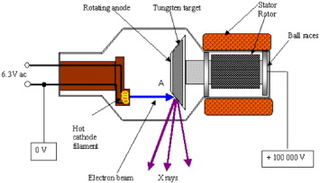
Figure 1 Schematic of an x-ray tube used for medical diagnostics.
The major design elements of the anode (the most critical part in the life of a high energy x-ray tube) are the speed of rotation for uniform heat distribution, thermal conductivity of the coating, interface and substrate, heat capacity of the substrate, thermal shock resistance of the substrate, adherence of the coating to the substrate and high temperature fracture/deformation of the substrate. High density graphite has for some time been the material of choice for the substrate to the anode, due to its light weight and relatively good adherence to the tungsten coating. Its use has some limits though—due to its low fracture toughness, modest thermal conductivity and thermal expansion coefficient mismatch with tungsten [3], several manufacturers are looking for an alternative substrate material. The following sections discuss the development and use of a ceramic matrix composite, which is specifically developed for this particular application.
2. Advanced composites as substrate solution
Aluminium nitride has received considerable attention in recent years due to its high thermal and mechanical properties and the material is currently employed in thermal management applications. AlN single crystals exhibit thermal conductivity [4] values of up to 320 W m −1 K −1, whereas the thermal conductivity of polycrystalline AlN varies from 80 to 200 W m −1 K −1 according to the microstructure and composition of the sintered ceramic [5–8]. Hotpressed pure AlN shows bend strength values between 250 and 300 MPa and its elastic modulus E ranges between 300 to 310 GPa [9–11]. Good thermal stability, excellent thermal conductivity, good corrosion resistance towards molten metals, together with oxidation resistance at high temperature, makes AlN an attractive material for use as a special refractory in metal processing. Its low density (3.26 g cm −3) allows it to be used for thermo-mechanical applications where light weight is required. Its field of application is limited primarily due to its low fracture toughness and thermal shock resistance. In the particular case of a substrate for x-ray anodes, there is also the requirement for the material to be an electrical conductor. One solution is to mix the ceramic with a metallic powder in sufficient concentrations so as to convert it into a conductor. A metallic particle is expected to improve the mechanical properties and, depending on the thermal and electrical conductivity of the metallic phase, can render the composite electrical and thermal conductor.
Attempts have been made to improve the fracture toughness of AlN by adding a dispersed second phase in the ceramic matrix, usually in the form of whiskers having a thermal expansion coefficient near to AlN. Studies [11, 12] have shown that the bend strength of a whisker (SiC) reinforced hot pressed AlN composite containing 10 vol.% SiC goes up to 370 MPa and the tensile strength is improved from almost 120 MPa for pure hot pressed AlN to a value around 275 MPa. Solid solution formation in the AlN–SiC w system resulted not only in a chemical phase change but also in a morphological change. Whiskers were consumed as SiC diffused into equiaxed AlN grains, thus forming a solid solution interphase at the grain boundaries. Studies concerning the effect of a ductile metallic phase addition (Al) were also carried out [13, 14] with a view to further improve the mechanical behaviour of AlN. Pure aluminium, due to its ductile nature, was used to improve the mechanical properties of the composite at room temperature, but its low melting point was a limiting factor in high temperature applications [15]. The addition of Cu in AlN was also studied, purely for thermal management applications [16]. Metallic phase added to different oxides and carbides, sintered together as a particulate reinforced ceramic matrix composite, has shown improved mechanical, thermal and electrical properties. Several recent works have shown the obviously positive effect of metallic phase addition in alumina, mullite and zirconium carbide [17–19]. A refractory metal with high thermal conductivity could thus be an ideal choice as a second phase additive.
The choice of refractory metals can either be tungsten or molybdenum, the two metals which are commonly used in x-ray tubes as targets. These are commercially available in powder form. Experiments were conducted using tungsten as an addition in order to increase the fracture toughness and eventually to render the composite as a conductor [20]. The addition of tungsten gives excellent mechanical properties to the composite and renders it an electrical conductor at 20–22 vol.% concentration. The only disadvantage is that tungsten has a much higher density than molybdenum, making the target anode heavy and difficult to rotate for cooling purposes. In previous works it has been shown [21, 22] that hotpressed AlN–Mo mixtures present a homogeneous and dense structure with measured density as high as 97% of the theoretical density (figure 4). Molybdenum has a much lower density than tungsten (d th =10.2 g cm −3), its melting point of 2610 °C is sufficiently high for this particular application, its high thermal conductivity (138 W m −1 K −1) and its thermal expansion coefficient are very near to those of pure hotpressed AlN (table 3). Energy dispersive x-ray (EDX) analysis [20] of the interface between AlN and Mo shows the absence of any secondary phase or solid solution, which if present could degrade the thermal and mechanical properties of the composite. Thermal conductivity measured at room temperature [23] for a series of AlN–Mo composites showed that its mean value increased from 78 W m −1 K −1 for pure hotpressed AlN to almost 104 W m −1 K −1 for a composite containing 20 vol.% of Mo. It was also shown [22] that the bend strength and fracture toughness of AlN–Mo composites increased as a function of metal phase concentration. The three-point bend strength increased from 270 MPa for pure hot pressed AlN to a value of almost 570 MPa for a composite containing 40 vol.% of metallic phase. The fracture toughness measured by the single edge precracked beam (SEPB) technique also increased from 2.3 MPa m 1/2 for pure AlN to a value of 6.9 MPa m 1/2 for a composite containing 40 vol.% of metallic phase [22]. This improvement in the mechanical and thermal properties of composites was attributed to the relatively ductile nature of Mo, to its higher mechanical resistance and to an adherent interface between the Mo grains and the AlN matrix. The absence of secondary phases at the interface played an important role in developing a perfect contact between the matrix and dispersed metallic particles and reducing the thermal contact resistance at the interface. The present work is an overview of the development of this composite, the present status of research on this group of ceramic matrix composites and its most recent applications. The final sections of the present paper discuss the sintering of large size anodes (74 mm diameter) through uniaxial pressing.
3. Experimental
3.1. Starting powders
Aluminium nitride powder was produced and supplied by H C Starck Berlin with a specific surface area of about 4 m 2 g −1. Its principal elements are given in table 1 where we note that oxygen is the main impurity. The size distribution, studied using the sedigraphy technique (Sedigraph 5000 D, Micromeritics), is presented in figure 2, which shows that most particles have sizes varying between 0.3 and 5 μm. The molybdenum powder was furnished by Prolabo, France. This powder is 99.9% pure, showing a relatively narrow size distribution (figure 2).
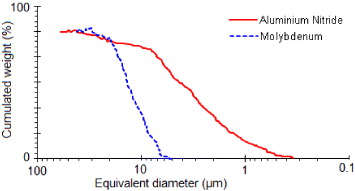
Figure 2 Size distribution of AlN and Mo powders measured by the x-ray sedigraphy technique.
Table 1. Composition of the AlN powder, as given by H C Starck, Berlin.
| % weight | > 64.5 | 33.2 | 1.8 | 0.05 | 0.01 |
3.2. Sintering conditions
Pure AlN and a mixture of AlN–Mo containing an incremental increase in Mo vol.% were hotpressed. The mixtures were prepared by dry milling in a multiaxial Turbula mixer, for a period of 24 h. Since AlN formed the continuous majority phase, the sintering conditions were kept similar to those commonly employed for the hotpressing of pure aluminium nitride [24]. The powders were sintered using graphite hotpressing moulds with 30 mm inner diameter. A thin BN film was deposited on the inner wall of the mould in order to avoid any interaction between the powder and graphite, as well as to facilitate the sample removal process after sintering. The sintering was performed under nitrogen (600 ml min −1). Figure 3 shows the temperature and pressure cycles employed during hotpressing. The sintered samples were in the form of 30 mm diameter discs. These were milled using a high speed diamond wheel, to a thickness of 4 mm. All samples produced under these conditions exhibited a densification of more than 97% with an open porosity content of less than 1.5%.
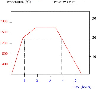
Figure 3 Temperature and pressure cycles used during the hotpressing of AlN–Mo mixtures.
Figure 4 presents the microstructure of a hotpressed sample containing 25 vol.% of molybdenum (AM25). The structure is composed of metal particles embedded in the ceramic matrix, having almost the same size as the initial molybdenum powder particles. No partial orientation of molybdenum particles, due to uniaxial pressing, is observed and the structure seems to be randomly dispersed.
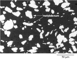
Figure 4 The microstructure of a hotpressed AlN–Mo composite (AM25) containing 25% Mo by volume.
4. Electrical resistivity of the composite
4.1. Four point Valdes method
This method is commonly used for the electrical resistivity measurement of semiconductors. It employs four points in contact with the sample surface, two of them are used to measure the current intensity I and the other two for the measurement of potential difference V (figure 5). Electrical resistivity ρ is calculated using the Valdes equation for four points in line configuration with a distance d (in cm) between each point:

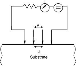
Figure 5 Schematic of a four points Valdes method for electrical resistivity.
4.2. Electrical resistivity as a function of molybdenum concentration
Figure 6 shows an important decrease in the electrical resistivity for compositions containing 0.2–0.22 volume fraction of molybdenum in the AlN matrix. For higher concentrations the composite behaves like an electrical conductor. This type of behaviour was studied earlier [25, 26]. In the case of solid electrolytes such as AgCl and LiI, after addition into Al 2 O 3 the presence of a space charge layer at the surface of the electrolyte particles affects the electrical properties. Very similar behaviour is also observed by Yu et al [27], whereas Gao et al [28] report a slightly lower value of molybdenum concentration for the percolation threshold. They observed the threshold of electrical conductivity for Mo concentration around 15 vol.%. This difference may be due to the fact that they subjected the composite to a high frequency signal, thus modifying the disposition of the space charge layer due to external field effects. This layer is responsible for the increase in charge carrier concentration inside the dielectric matrix.
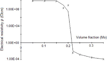
Figure 6 Variation of the electrical resistivity ρ of AlN–Mo composites, as a function of molybdenum concentration (Valdes technique).
When two surfaces having different work functions are in contact, a charge transfer takes place in such a manner that the one having the higher work function value is enriched in electrons. This transfer of charge at the surface is responsible for the formation of a space charge layer. Figure 7 illustrates a simplified form of such an interface at equilibrium state. Energy levels for the valence band, conduction band and Fermi level are represented by ε v , ε c and ε f , respectively, λ is the Debye length, q is the charge and ϕ m and ϕ s are the potentials of the metal and semiconductor surface.
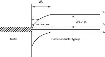
Figure 7 Schematic illustration of the formation of a space charge layer at the metal–ceramic interface.
X-ray diffraction (XRD) analysis of the sintered AlN–Mo surface does not show any extra peak except those attributed to AlN and Mo as shown in the figure 8. The presence of a stable secondary phase at the grain boundaries, belonging to the system Al–O–N [24, 29], which is favourable for good densification of AlN in the absence of sintering additives, cannot be identified on the x-ray diagram. This phase probably exists superficially and in a very small quantity which makes it impossible to identify through XRD. Its formation can be explained by the presence of oxygen (1.4% by weight) at the surface of the AlN powder [29]. This phase is believed to be responsible for the excellent quality of the interface, giving strength to the composite as well as providing the necessary contact for heat to flow resulting in superior thermal conductivity, as explained in the previous section.

Figure 8 XRD pattern of a polished surface of AM25 (25 vol.% of Mo).
5. Thermal shock resistance of the composite
5.1. Theory of thermal shock
Thermal stresses in a solid material are produced as a result of a temperature gradient. In the case of anisotropic materials or multiple phase materials such as composites, with each phase having different thermal constants, these stresses can be generated through a simple heating process. If we consider a perfectly elastic isotropic solid material, submitted to a limiting value of thermal stress σf under a temperature difference ΔTf , an equation of the following type can be written:

where E, υ and α are Young's modulus, Poisson's ratio and the linear thermal expansion coefficient, respectively. Equation (

where σ0 is called the 'stress reduction coefficient', a dimensionless coefficient whose value is situated between 0 and 1. The heat exchange at the solid surface can be described by Biot's modulus (β) defined by the following relationship:

where h is the surface heat transfer coefficient, rm defines the mean sample size and κ is the sample thermal conductivity. When the value of β is high, σ0→1, which signifies severe thermal shock conditions. Application of this thermoelastic approach underlines that materials having higher values of mechanical resistance and thermal conductivity, small size, low thermal expansion coefficient and Young's modulus, would show good thermal shock resistance. But the thermoelastic approach does not describe the stability of existing cracks in terms of energy balance, because it is supposed that a crack, once initiated, will instantaneously produce fracture in the material. Meanwhile, it is known that some porous refractory materials possess good thermal shock resistance, even in the presence of poor thermal conductivity and bad mechanical properties. Hasselman [30, 31] emphasized that the crack stability comes from the elastic energy stored in the solid at the moment of fracture. The elastic energy for an isotropic solid can be written as

where E0 and υ0 are the Young's modulus and Poisson's ratio of a non-fractured solid, N is the crack density and l is the crack size. Considering the total internal energy as the sum of the surface energy and stored elastic energy, the critical temperature difference ΔT c required for crack instability could be given as

where γ is the specific surface energy of the material. This approach provides arguments to support that the thermal shock resistance could be expressed not only on the basis of critical temperature difference but also on the basis of critical elastic energy and critical crack size.
5.2. Measurement of thermal shock resistance
Thermal shock measurement equipment (figure 9) was composed of
- a vertical furnace (super kanthal) working up to 900 °C under normal atmospheric conditions,
- a programmable pneumatic sample holder fixed at the upper end of the furnace, which allowed maintenance of the sample inside the furnace for a given time and for it to be rapidly quenched in a water bath (the quenching bath was maintained at 25 °C) and
- a control panel attached to a personal computer which permitted the regulation of parameters like furnace temperature, sample heating time, quenching temperature and quenching time.
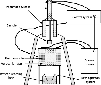
Figure 9 Schematic diagram of the thermal shock resistance measurement equipment.
Figure 10 shows the variation of sample temperature inside the furnace as a function of time. It could be seen in this figure that the sample attained equilibrium after about 2 min. Samples after quenching were treated with a fluorescent liquid (ARDOX 970 P2) and observed under an ultraviolet lamp to detect the presence of surface cracks. Finally, samples were tested to measure their three-point bend strength.
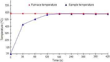
Figure 10 Sample temperature variation with dwell time inside the furnace.
Mean values of three-point bend strength for pure AlN and AM25 (composite containing 75 vol.% AlN and 25 vol.% Mo) are shown in table 2.
Table 2. Mean values of three-point bend strength, of AlN and AM25, after thermal shock treatment at different temperatures.
| AlN | 25 | 0 | 300 |
| 150 | 125 | 285 | |
| 250 | 225 | 311 | |
| 300 | 275 | 273 | |
| 350 | 325 | 273 | |
| 400 | 375 | 194 | |
| 450 | 425 | 72 | |
| 550 | 525 | 62 | |
| AM25 | 25 | 0 | 500 |
| 325 | 300 | 475 | |
| 430 | 405 | 482 | |
| 500 | 475 | 478 | |
| 600 | 575 | 301 | |
| 700 | 675 | 220 | |
| 750 | 725 | 137 | |
| 800 | 775 | 120 |
It could be seen from the results that AM25 exhibits a critical temperature difference for thermal shock (ΔT c ) which is around 550 °C, as compared to that of pure hot pressed AlN which is about 350 °C. This important increase in thermal shock resistance of the composite can be explained on the basis of its thermal and mechanical properties.
The critical temperature difference for thermal shock or the first parameter for thermal shock resistance, according to the thermoelastic approach, is directly proportional to the mechanical strength (σf
) and inversely proportional to Young's modulus (E) and the thermal expansion coefficient (α) of the material. The addition of 25 vol.% Mo does not affect the values of E, υ and α in a notable manner, but σf
is almost doubled, as shown in table 3 [32]. This partly explains the increase in thermal shock resistance of the composite. Moreover, due to the high thermal conductivity of AM25, according to equation (
Table 3. Some common physical and mechanical properties of pure hotpressed AlN, molybdenum and AM25 [33].
| Specific weight (g cm −3) | 3.26 | 4.995 | 10.2 |
| Melting or decomposition | ∼ 2450 | – | 2610 |
| point (°C) | |||
| Thermal conductivity | 78 | 100 | 138 |
| at 20 °C (W m −1 K −1) | |||
| Thermal diffusivity | 9×10⁻⁶ | 1.2×10⁻⁵ | – |
| at 750 °C (m 2 s −1) | |||
| Three-point bend strength (MPa) | 300 | 500 | – |
| Fracture toughness (MPa m 1/2) | 2.3 | 6.4 | – |
| Young's modulus (GPa) | 313 | 323 | 322 |
| Linear thermal expansion | 6.5 | ∼7 | 7 |
| coefficient (10−6 K −1) | |||
| Poisson's ratio (υ) | 0.24 | 0.257 | 0.3 |
| Specific heat | 800 | 525 | 251 |
| at 20 °C (J kg −1 K −1) |
6. Sintering of the anode
Sintering of large size objects in AlN remains complex due to the very high loads required to attain the necessary pressures for hotpressing. The problem has more magnitude when these large size pieces have complex shapes. Sintering of small size discs (ϕ between 8 and 30 mm) requires relatively small size moulds and loads less than 2000 kg, when sintering through uniaxial pressing. Sintering of anodes of 74 mm diameter, as shown in figure 11, needs loads of more than 4000 kg and a specifically designed graphite mould of 125 mm diameter. This mould has to be specifically designed to obtain sintered forms which are very near to the finished forms, in order to reduce the eventual machining operations to their minimum. Sintering cycles have to be modified accordingly and the volume effect is considered in all the phases of the sintering cycle. The sample attains equilibrium temperature in a much longer time, the vacuum takes a long time to be stable and the gases desorbed during sintering need a larger space between the mould walls, or else they leave large porosity behind them. All these make sintering of such a large component a tremendous technical and scientific challenge. The following sections present the experimental details concerning the sintering of large diameter AM25 substrates.
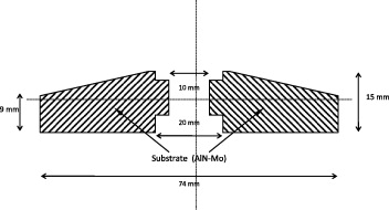
Figure 11 Section of a 74 mm diameter anode substrate.
6.1. The graphite mould
The graphite mould used for hotpressing was specifically designed to sinter components as close as possible to their final shape. These composites are very hard to machine, hence such a mould was necessary in order to reduce the time and cost of final operations. A section of the mould is presented in figure 12. It is entirely constructed with high modulus graphite ELLOR 9 (Le Carbone Lorraine). The central part is supplied with a graphite ring of 18 mm diameter and 2 mm thickness, which slips over the graphite rod forming the central axis. Another ring of 18 mm diameter and 6 mm thickness is placed after the powder is introduced in the mould. These rings form the cavity required for the placement of screws on the anode substrate. The lower plate is made with an angle of 15° which corresponds to the anode form. A thin boron nitride layer is projected on the inner surface of the mould to facilitate the demoulding process after sintering.
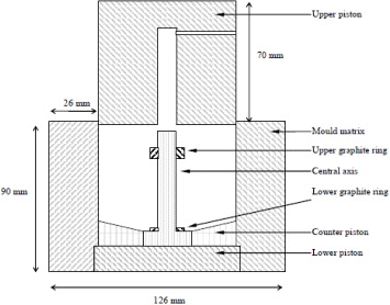
Figure 12 Section of the graphite mould.
6.2. Sintering cycle
The sintering cycle is modified in a manner to accommodate the large size of the sample. Figure 13 illustrates the temperature and pressure cycles used during the hotpressing of the anode. The heating rate, dwell time and pressures have been changed from the previously discussed sintering cycle (figure 3) in order to accommodate the longer times required for attaining equilibrium as well as limitations to the strength of graphite to sustain loads at high temperature.
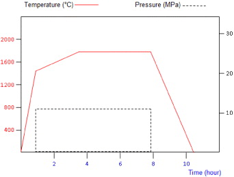
Figure 13 The modified sintering cycle for 74 mm diameter anodes.
Figure 14 presents the microstructure of the sample cut from these substrates, showing a similar microstructure as that observed in figure 4 with a small increase of porosity. We also remark that metallic grains possess a slight round form, which can be due to longer sintering cycles. The sintering temperature of 1800°C under a slightly lower pressure has most probably created the slight evaporation from the surface of the molybdenum grains, resulting in the removal of sharp edges observable in figure 4. The presence of porosity is not a good sign for the eventual application of this composite under a vacuum. The pressure of about 12 MPa applied during the sintering is less than initially desired. To design hotpressing furnaces capable of generating higher loads is a strong technological challenge, as industrial anodes have to be produced in the future with diameters exceeding 74 mm.
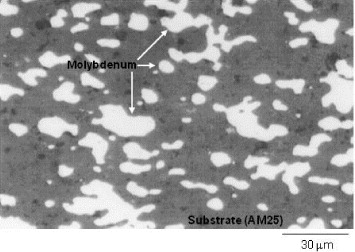
Figure 14 The microstructure of the hotpressed 74 mm anode (AM25).
7. Conclusion
Aluminium nitride co-sintered with molybdenum promises to be a new generation of ceramic matrix composites. This system has generated a lot of interest lately in chemical, mechanical and electrical applications. In this work, the basic sintering characteristics of the composite are discussed. The study of electrical resistivity has shown that the composite becomes an electrical conductor for molybdenum concentrations between 20 and 22 vol.%. This value is consistent with similar work done by other authors on ceramic metal composites. This also indicates that the ceramic–metal interface is strong and contact is intimate. There are no oxide phases produced at the interface, otherwise the electrical resistivity would have been higher. The XRD also shows no phase present at the interface. The microstructure is homogeneous with very little porosity in the matrix.
The thermal shock resistance of pure hotpressed AlN and a composite produced through a mixture of 75 vol.% AlN and 25 vol.% Mo was measured in order to study the influence of molybdenum addition on the thermal shock behaviour. The thermal shock resistance results have shown that an AlN–Mo composite containing 25 vol.% of dispersed metallic phase (AM25) exhibits a ΔT c value of about 550 °C compared to a mean ΔT c value of almost 350 °C measured in the case of pure hot pressed AlN. Moreover, the bend strength of AM25 without any thermal treatment was found to be almost two times as high as that of pure hot pressed AlN, which is in agreement with earlier work. This excellent behaviour of the composite against thermal shock is attributed, on one hand, to better mechanical properties (high bend strength and fracture toughness) and on the other hand, to better thermal conductivity of AM25.
Sintering of large size components using uniaxial pressing at high temperatures brings technical and scientific challenges. As the actual anode diameter is 74 mm, a special graphite mould is fabricated to sinter the anode in its actual size and shape. The sintering cycle is modified accordingly. The sintering result shows that pressure and time are two very important variables. These parameters need to be studied in depth when the size of the sintered object is increased otherwise the density of the sintered object is not homogeneous and its microstructure remains porous. Further investigation on this effect needs to be conducted so as to decide on an efficient and accurate sintering cycle.